Wireless Microphone Transmitter And Receiver Circuit Diagram FM Transmitter Circuits 38; Home Automation Projects 6; Inverter Circuits 29; LED & Light Circuits 285. LED Flashers 55; Mobile Charger Circuits 13; Motor Speed Control Circuits 41; Power Banks Circuits 14; Power Supply Circuits 112; Printed Circuit Board - PCB 175; Radio and RF Circuits 69; Safety & Security Circuits 58; Sensors and Modules The circuit uses the SN7413 NAND chip as oscillator to generate a carrier frequency of about 100 Mhz which lays inside the FM radio frequency range (88 Mhz - 108 Mhz). This transmitter has a range of about 50 m. Being low-powered, most transmitters typically have a short range of 100-300 feet (30-100 meters), depending on the quality of the receiver, obstructions and elevation. Typically they broadcast on any FM frequency from 87.5 to 108.0 MHz in most of the world . In this project we design the circuit in such a way that ,the circuit will collect

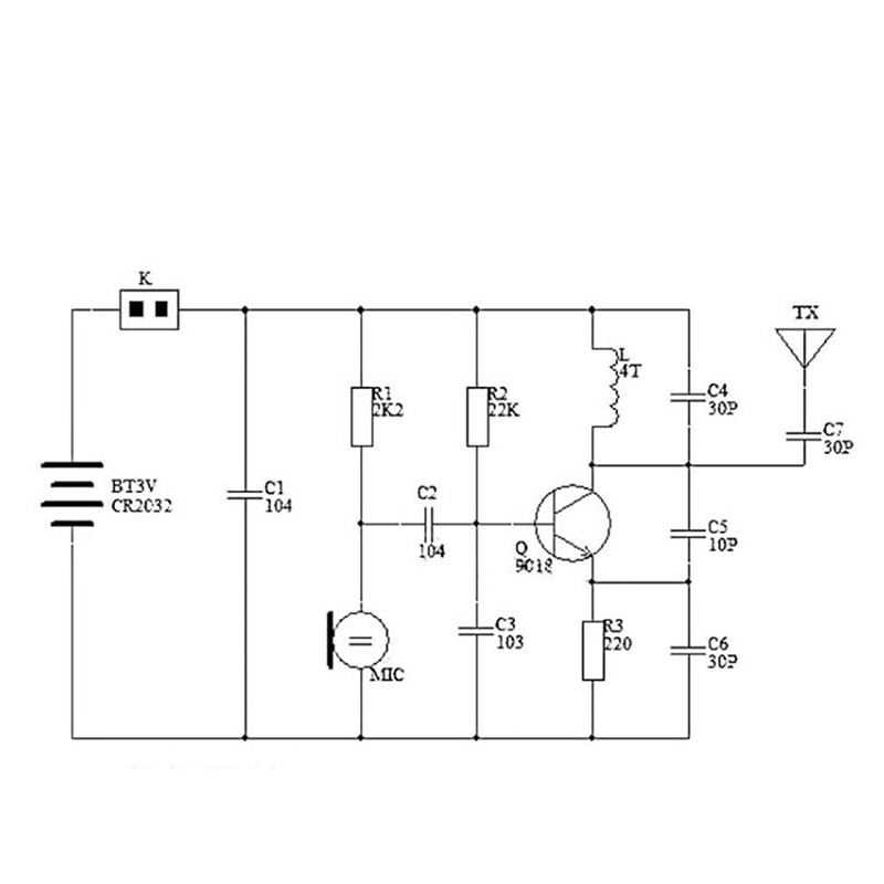
This project will demonstrate how a simple 88MHz-110MHz FM transmitter can be built using very few parts and just one transistor. The transmitter can be attached to just about any electronic circuit to transmit information (both analog and digital), to create spy bugs, simple satellite circuits, and even radio coms. DIY FM Transmitter Schematic
The Simplest FM Transmitter Ever... Without Coil/inductor Circuit Diagram
I designed a compact PCB layout for Art Swan's miniature FM transmitter circuit using Fritzing. Use this step as your reference for the assembly. _____ About The Circuit: These is the exact description of Art Swan, the circuit's Author, "This miniature transmitter is easy to construct and can be picked up on any standard FM receiver. It has a

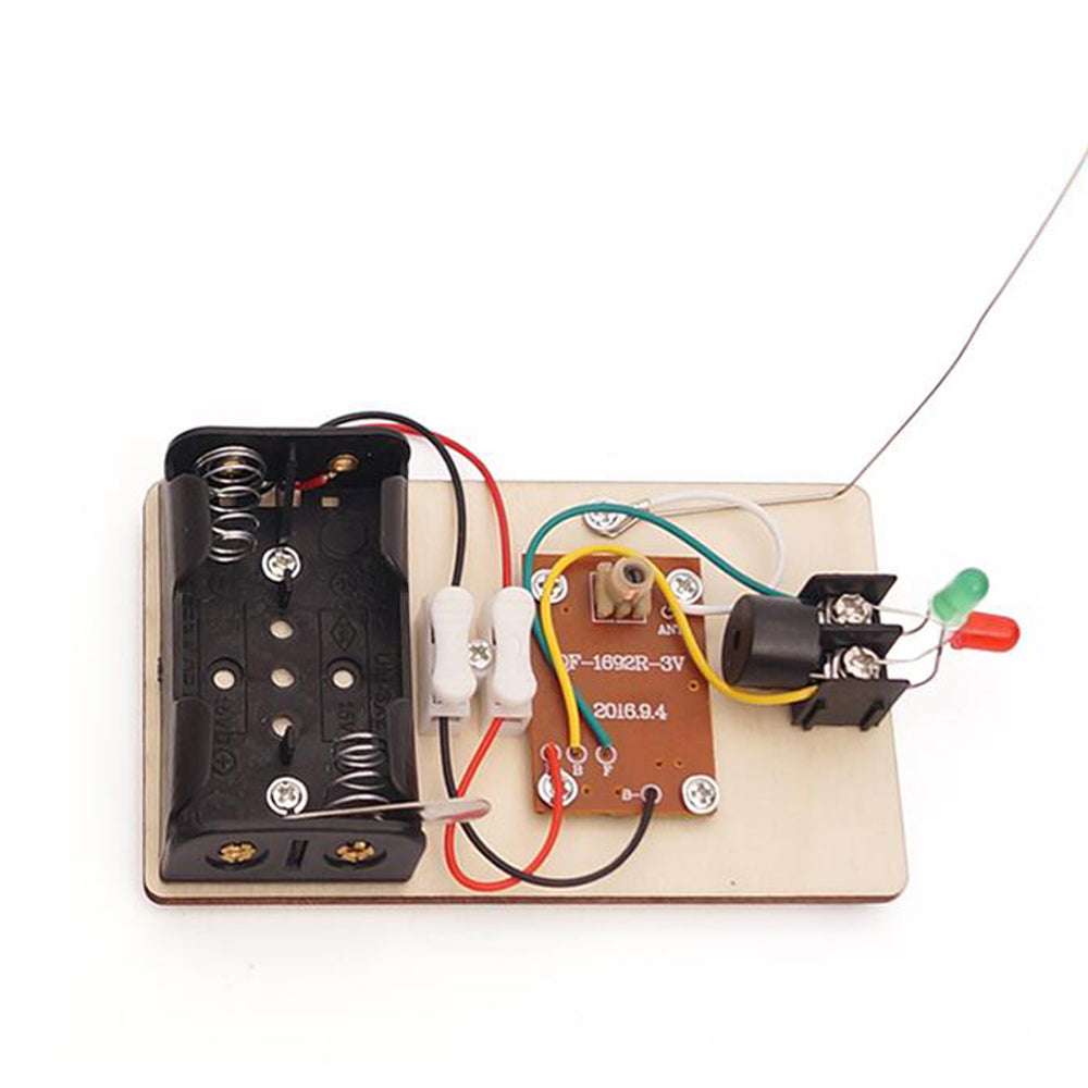
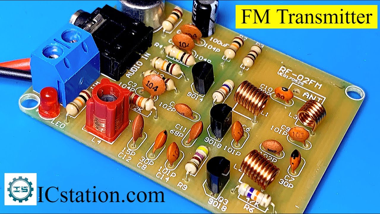
This is how this simple FM transmitter circuit looks on breadboard . The audio output signal from the microphone is usually small, the first transistor thus performs the job of amplifying that signal to a level good enough for transmission. 96 MHz Arm® Cortex®-M33 core + multiprotocol radio subsystem supporting Matter, Thread, Zigbee
How to Make an FM Transmitter Circuit Diagram
Building a simple transmitter and receiver is the quickest way to get started on your journey into the world of RF. It is also a lot of fun. This tutorial provides an excellent introduction to building a simple digital communication system. Martyn Davies provides a good overview of modulation, RF circuits and programming with an Arduino. Here we'll discuss how to build small FM transmitter circuits using 10 different methods, one that consists of wire link from the transmitter to the receiver, and the other which is completely wireless and can be used to eavesdrop a particular conversation over a range of about 30 meters, over an ordinary FM radio. All the FM transmitter With the intricate circuit of your DIY FM transmitter taking shape, the next pivotal step involves the seamless integration of the antenna, a crucial component that enables the transmission of your modulated audio signals into the surrounding space. Listen for the broadcasted audio on an FM radio receiver within the vicinity, ensuring that