Why is this ideal diode bridge rectifier simulation in LTSpice not Circuit Diagram Guide on creating a bridge rectifier circuit with 1N4007 diodes. Creating a bridge rectifier with four 1N4007 diodes is not a challenging undertaking. By turning the terminals of the four diodes in a particular way, a bridge rectifier can be created quickly. These steps can be used to create a bridge rectifier: Use four 1N4007 diodes. Learn how a rectifier diode works and how it can be used in power supplies to convert alternating current into direct current. Also get a detailed explanation of the three standard rectifier configurations- half-wave rectifier, full-wave rectifier, and bridge rectifier. Also, find out how to build a bridge rectifier circuit through three simple steps.

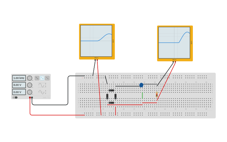
Now, a bridge rectifier on its own doesn't truly convert AC as we found out in the USB charger circuit demo. It only converts AC into a DC wave pulse (or DC oscillation). It requires some capacitors to clean up the pulse and create a more DC like signal. How to Make a Bridge Rectifier Circuit using 1N4007 Diodes. Making a bridge rectifier using four 1N4007 diodes is not at all a difficult task. Simply by twisting the terminals of the four diodes in a specific pattern, a bridge rectifier can be made within seconds. Your bridge rectifier design is ready and may be used for the intended The full wave rectifier circuit consists of two power diodes connected to a single load resistance (R L) with each diode taking it in turn to supply current to the load.When point A of the transformer is positive with respect to point C, diode D 1 conducts in the forward direction as indicated by the arrows.. When point B is positive (in the negative half of the cycle) with respect to point C
Simple Bridge Rectifier Circuit Circuit Diagram
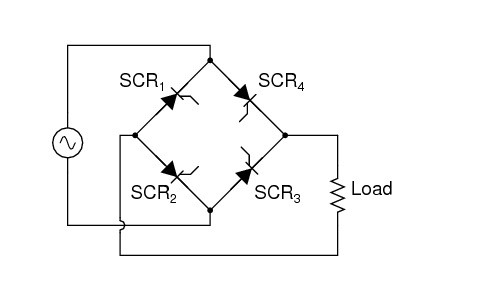
The Rectifier Diode. The diode bridge rectifier circuit is a very simple circuit made up of just four rectifier diodes connected in a square shape. A diode allows current to flow in one direction only (from the anode and to the cathode), which makes it perfect for converting from AC to DC.

Full wave bridge rectifier is formed by connecting four diodes together in such a way that their arms form a bridge, hence the name bridge rectifier. In bridge rectifier, volatge can be applied to the diode bridge through a transformer or directly through the AC signal without the transformer. Here we are using 6-0-6 center tapped transformer In a bridge rectifier circuit, two diodes conduct during each half cycle and the forward resistance becomes double (2R F). In a bridge rectifier circuit, Vsmax is the maximum voltage across the transformer secondary winding whereas in a centre tap rectifier Vsmax represents that maximum voltage across each half of the secondary winding. Unlike half-wave rectifiers, which discard the negative amplitude, the bridge rectifier preserves both polarities, classifying it as a full-wave rectifier. A key advantage of a bridge rectifier is that it eliminates the need for an expensive center-tapped transformer, thereby reducing both the size and cost of the circuit.