What are series and parallel connections in a circuit Circuit Diagram Combining Series and Parallel Circuits. In complex systems, series and parallel circuits are often combined to balance voltage, current, and reliability. Example: In a solar power system: Solar panels may be connected in series to increase voltage. These series strings are then connected in parallel to increase current capacity and ensure Differences Between Series vs Parallel Circuits . One way to understand the difference between a series and a parallel circuit is by looking at a similar system: a freeway. A parallel circuit is like a freeway. Ramps allow cars to exit and enter a freeway without interrupting the main highway. A parallel circuit has many off- and on-ramps.
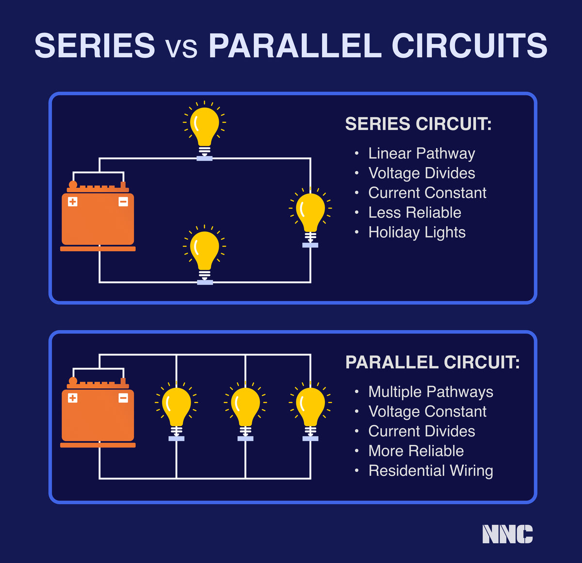
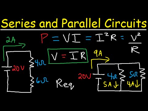
A series or a parallel circuit is determined by the arrangement of the circuit elements and the flow of current in that circuit. Series Circuit If all the elements of a circuit are arranged in such a way that the magnitude of current that flows through each element is equal to the total current in the circuit, then the circuit is said to be a The components of the electrical DC circuit are mainly resistive, whereas components of the AC circuit may be reactive as well as resistive.. Any electrical circuit can be categorized into three different groups - series, parallel, and series-parallel. So for example, in the case of DC, the circuits can also be divided into three groups, such as series DC circuit, parallel DC circuit, and

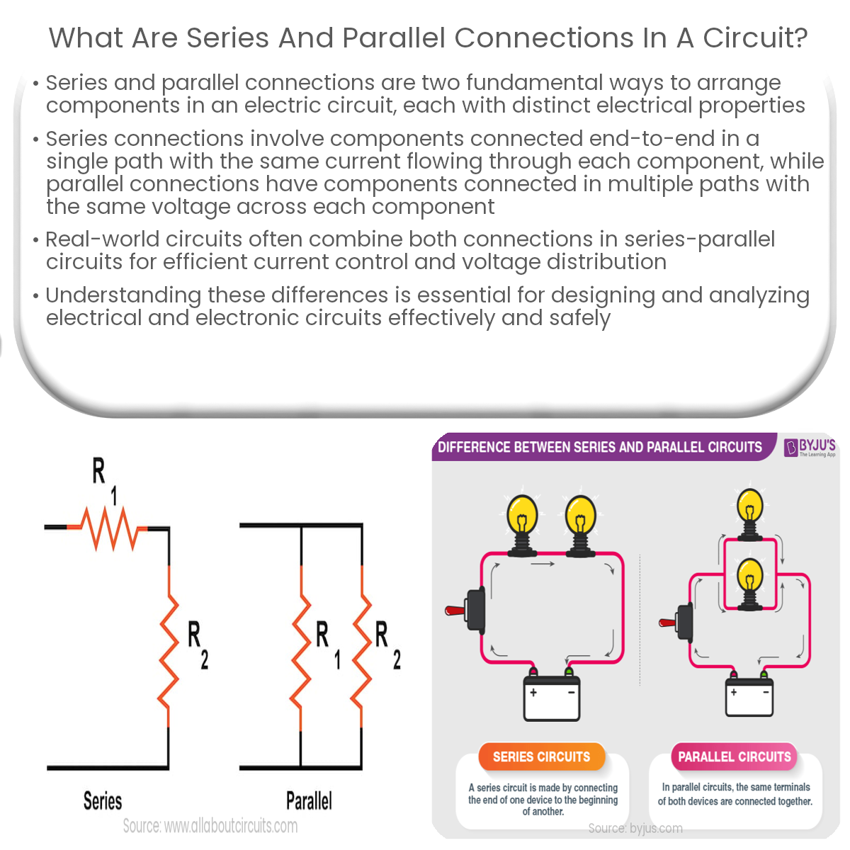
Difference between Series and Parallel Circuits Circuit Diagram
Parallel vs. Series Circuits Understanding the Difference with a Practical Example . In the world of electrical engineering, understanding how different circuit connections work is essential for designing efficient and safe electrical systems. Two fundamental types of circuits are parallel circuits and series circuits. While both serve the same
Both series and parallel circuits are types of electrical circuits. Any number of components like resistors etc. can be connected in both series and parallel circuits. The purpose of the parallel of both series circuits is to control the flow of current. Difference Between Series and Parallel Circuits. The differences between Series and
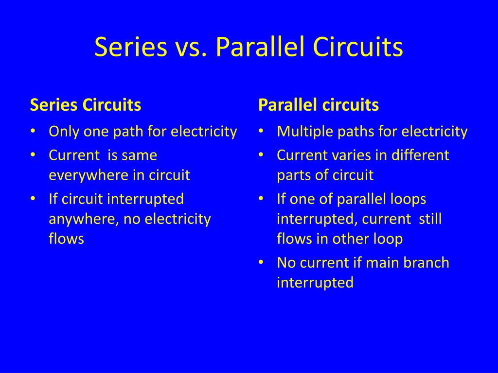
Series and parallel circuits Circuit Diagram
All of the resistors, as well as the battery, are connected between these two sets of points. This means that the same voltage (V) is dropped across all components in a parallel circuit. Series vs Parallel Circuit Review: In a series circuit, all components are connected end-to-end, forming a single path for current flow. A series circuit with a voltage source (such as a battery, or in this case a cell) and three resistance units. Two-terminal components and electrical networks can be connected in series or parallel.The resulting electrical network will have two terminals, and itself can participate in a series or parallel topology.Whether a two-terminal "object" is an electrical component (e.g. a resistor) or