Voltage Regulator Tutorial Circuit Diagram Types of Voltage Regulators. In general, we use electronic devices to build a voltage regulator. They have a lot of types. But we may put all in basic 2 types of voltage regulators viz., Shunt voltage regulator; Series voltage regulator; The shunt voltage regulator—we will place them in parallel with a load. Often use a resistor to reduce the This is great for applications where you need multiple discrete voltages for different devices within a single circuit, as you can use voltage regulators to step-down from a single higher output source! Most voltage regulators have 3 pins: Input - This is the input voltage from the original source. For example a battery, or power supply.

The voltage regulator may use a simple feed-forward design or may include negative feedback. The design can consist of either an electromechanical mechanism or electronic components. To understand its working, consider the circuit shown in the figure below. A voltage regulator circuit is installed between the supply voltage (input) and the Next up in our voltage regulator tutorial, we need to talk about some additional caveats of using voltage regulators that you should be aware of. If you do the math on a 5 volt circuit drawing 500 milliamps (or .5 amps) with a 12 volt input voltage, that turns out to be 3.5 watts of heat generated (or wasted). If you're looking for lower
Voltage Regulators (A Practical Guide with Circuits) Circuit Diagram
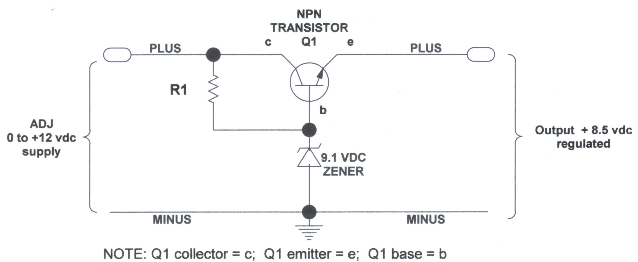
A linear regulator operates by using a voltage-controlled current source to force a fixed voltage to appear at the regulator output terminal (see Figure 1). The control circuitry must monitor (sense) the output voltage, and adjust the current source (as required by the load) to hold the output voltage at the desired value. The Here we used a Zener as the reference and the transistor Q1 as a series regulator doing the hard work. R2 provides bias to turn Q1 on and supply a much smaller current through the Zener D2. If Vout is 5V, the base-emitter volt drop of 0.6V would be added to that, so D2 would need to be 5.6V (commonly available), and R2 would now have to supply the collector current/hfe of the transistor (say

A voltage regulator can take those 9V as input and create a nice and stable 5V output that you can use to power your device. Or if you need different voltage levels for a circuit you're building. Let's say you have a circuit with a microcontroller that needs 5V and a motor that needs 12V. The purpose of a voltage regulator is to provide a constant output voltage regardless of the load resistance. In other words, an ideal regulator would produce a voltage that is (for example) exactly 3.3 V when connected to a 100 kΩ load and exactly 3.3 V when connected to a 5 Ω load. This is a USB 5V to 1.5V step-down converter circuit using the LM317 voltage regulator. When we use a cheap MP3 Player which uses only one 1.5V AA battery as its power supply. Gel cell battery charger circuit It can charge any size of the Gel cell battery and extend the life of the Gel Cell battery. While the circuit is running, the LED