Voltage Divider Circuits Circuit Diagram Learn how to create a voltage divider circuit with two resistors and an input voltage, and how to calculate the output voltage using a simple equation. Explore real-world applications of voltage dividers, such as potentiometers, resistive sensors, and light level measurement. Learn how to use the voltage divider rule to calculate the voltage drops across resistors in series. See examples of voltage divider circuits with two, three or more resistors and how to adjust the output voltage with a potentiometer or a sensor. Learn what a voltage divider circuit is, how it works, and how to calculate its output voltage. Explore the different types of voltage dividers (resistive, capacitive, and inductive) and their applications in electronics and measurement devices.

Learn how to calculate the voltage drop, resistance, current, and output voltage in a voltage divider circuit. A voltage divider is a simple circuit that can reduce voltage by distributing it among the components of the circuit.

Circuit, Equation, Applications, Solved Problem Circuit Diagram
Learn how to use a voltage divider circuit to create a smaller voltage from an input voltage with two resistors. Find the output voltage formula, a calculator, and examples of voltage divider applications.

Learn how to use voltage dividers to convert an input voltage into an output voltage that is a fraction of it. Explore resistive, capacitive and inductive voltage divider circuits with examples and applications.

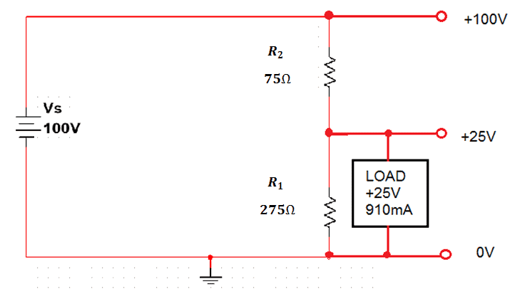
Voltage Divider Tutorial For Beginners Circuit Diagram
It is actually the divider voltage that we get from this circuit as the output. Equation of Voltage Divider in Unloaded Condition. The simple voltage divider circuit with reference to the ground is shown below. It has two electrical impedances (Z 1 and Z 2) or any passive components connected in series.These impedances can be resistors, inductors, or capacitors.