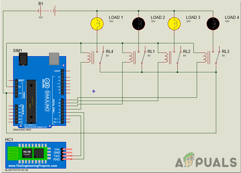
Voice Controlled Home Automation and Security System Circuit Diagram The Voice Activated Home Automation system will help us control different loads (electrical appliances) with simple voice commands. This kind of system is very useful for people with disabilities. Further, the project can be expanded by adding different sensors (light, smoke, etc.). Construction and Output Video Circuit and working of the voice controlled home automation system Circuit diagram of the voice-controlled home automation system is shown in Fig. 3. The circuit consists of Arduino Mega 2560 board (Board1) for comparing the input string received through Bluetooth with the stored string to give output to digital pin 6 of Board1 to control the In this home automation project using Arduino, we will use voice function to control home devices. This project is similar to home automation using Bluetooth. In that project, we used the S2 Terminal application however in this project we will use AMR_Voice Android application. This application is free and very easy to use.
Even a Raspberry Pi voice control can be easily built by yourself. Because such a speech recognition is of course very beneficial for home automation. In this tutorial, I'll show you how to digitize speech through a microphone, convert it into text, and then respond to it. The voice recognition feature can already be tested here (in Chrome). The complete circuit diagram for the Voice Controlled Home Automation Using Arduino is shown below. The schematic diagram for the project is very simple. A Hi-Link 5V AC-DC module is used as the power source. The AC input is directly connected to the power supply module. The 5V output from it will be used to power the entire control circuit. Introduction. In the previous Home Automation Series, we have learned how to make RF Based, IR Remote Control, Bluetooth Control, and GSM Based home automation systems, where we have controlled home appliances by sending text messages or pressing the button.But, in this project, we will control the AC home appliances by sending Voice Command from our smartphone.
Voice Activated Home Automation: Control Made Simple Circuit Diagram
Step 2: Voice Controlled Home Automation Circuit Diagram We are using a 3.5 mm jack male connector to connect with the speaker and a USB mic to connect with the raspberry pi. The bulb's connection with the relay module is simple, one terminal of the bulb is connected to the AC supply (neutral) and the phase of the AC supply is connected to By applying some electrical signal we can control our switches. To control the switch we are going to need a control here I am using Atmega328 microcontroller based Arduino Nano. To connect Our Home automation system with a smartphone are going to need a Bluetooth module. Here I am using HC-05. To power our system I am using 12v dc power supply Voice Controlled Home Automation: Hello there, In this instructable, I'm going to teach you to make a voice-controlled Home Automation. We'll just tap into our mobile and control our appliances by our voice. Then the 12v power supply reaches the relay circuit where it make's it to let the 220v AC current to go through it and make the