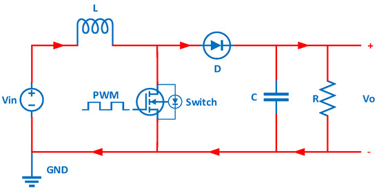
TwinDelayed Deep Deterministic Policy Circuit Diagram The boost converter (step-up converter) is used when the output voltage must be higher than the input voltage. As apparent from Figure 1., the inductor is in the input circuit, which means that this topology has no discontinuous input current. You can see an overview of basic power converters in the article DC-DC Converter Basic Characteristics and Formulas. So, a Boost converter is also called a step-up converter or step-up chopper. It is given the name "boost" because the obtained output voltage is higher than the supplied input voltage. It performs the reverse operation of the buck converter which converts higher DC input into lower DC output. The boost converter is used to step up an input The maximum output voltage of the boost converter is not limited by design but by the breakdown voltage of the MOSFET. 3. The inductor. Obviously, just any old inductor won't work. Inductors used in boost converters should be able to withstand the high currents and have a highly permeable core, so that the inductance for a given size is high.
A Practical Boost Converter Circuit Design using IC 555 Now let's refer to our fourth step-up converter design which will boost a 3.7 V input DC to 24 V output DC. This simple circuit is built using an IC 555 circuit for boosting USB 5V to 24V , or any other desired level.
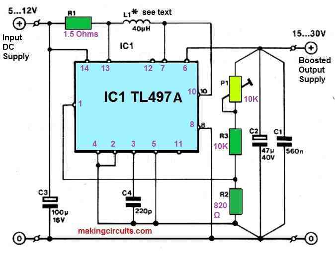
Boost Converter Design and Calculation Circuit Diagram
A boost converter (step-up converter) is a DC-to-DC power converter that steps up voltage (while stepping down current) from its input (supply) to its output (load). It is a class of switched-mode power supply (SMPS) containing at least two semiconductors (a diode and a transistor) and at least one energy storage element: a capacitor, inductor Next we need to calculate the MAX OUTPUT CURRENT the boost converter can output: = - This is the current switch limit of the boost converter. Example: = = 0.33A = = 0.45A. Step 7: Next we will calculate the MAX SWITCHING CURRENT, the Inductor will see. This value cannot exceed the ILIM value of the boost converter: Example: = 0.94A = 0.72A
Learn About The DC-DC Boost Converter Design, Circuit, Equations, Formulas, and Diagrams. Visit Today To Learn More! the inverting topology is based on the same basic principle as the non-inverting boost regulator, meaning the energy is stored in the inductor L1 during the "on" period of Q1 and transferred to the output load via the
Circuit Diagram, Working & Waveforms
A boost converter is basically a step-up chopper or step-up dc-to-dc converter by which we can obtain an output voltage greater than the input voltage. In other words, boost converters are regulator circuits that generate a voltage at the output side whose magnitude will be greater than or equal to the input applied voltage. A DC-to-DC boost converter circuit is a circuit that can convert a DC voltage into a larger DC voltage. So, for example, you may be able to convert a 5V DC voltage into 30V. A DC-to-DC converter works on the principle of an inductor primarily and a capacitor. When fed DC power, the inductor acts as a energy storage device for current. As long In this tutorial we will learn how to build and how a DC to DC boost converter works. The circuit is very basic using just one diode, an inductor and a capacitor. The switch will be a MOSFET transistor and to create the PWM signal we will use a 555 timer in the PWM configuration, boost adjustable controller or one Arduino NANO.
