The Transistor Circuit Diagram Learn how to identify the transistor type, pinout, and measure the voltage drop between its terminals using a multimeter in diode mode. Find out the expected voltages for NPN and PNP transistors and how to interpret the test results.
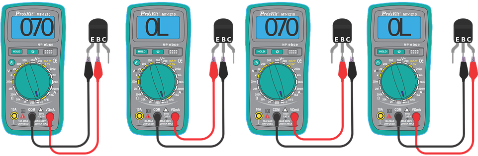
In the same manner, we can test a PNP transistor too. Step by Step Testing of NPN Transistor. Set the digital multimeter to Diode or Continuity range. Connect the Positive probe (Red coloured) of multimeter to the base terminal of the transistor. Connect the negative or common probe (Black coloured) of multimeter to the emitter terminal. To check a transistor in hFE mode, there are 8 pins slot in the multimeter indicated by PNP and NPN as well as E C B (Emitter, Collector and Base). Simply put the three pins of transistor in the multimeter slot one by one in different slots i.e. ECB or CBE (Rotary knob should on hFE mode).
How to Test a Transistor Using a Digital Multimeter Circuit Diagram
Learn how to use a multimeter to test transistors for voltage drop, continuity, and faults. Follow the step-by-step instructions for NPN and PNP transistors, and understand why testing is important for electronics projects. Finding BASE of Transistor:. As mentioned in the above tutorial, the common number found in the tests above is base. In our case, 2 nd terminal is Base and 2 is common out of 1-2 and 2-3.. 2 nd Method using DMM to find the Base of the Transistor.. If you follow the same pattern and connecting method of multimeter leads and transistor terminals one by one in the figure shown above, in fig "c
In this video tutorial we will guide you to learn how to check transistor is working or not using multimeterQuick Learning Guide for Multimeters: https://

How to Test a Transistor using Multimeter (DMM+AVO) Circuit Diagram
To test your transistor, first clamp the black probe of a multimeter to the transistor's base. Then, touch the red probe to the emitter and read the display to see if the resistance is high or low. Next, move the red probe to the collector, and check that the reading is the same as it was before.

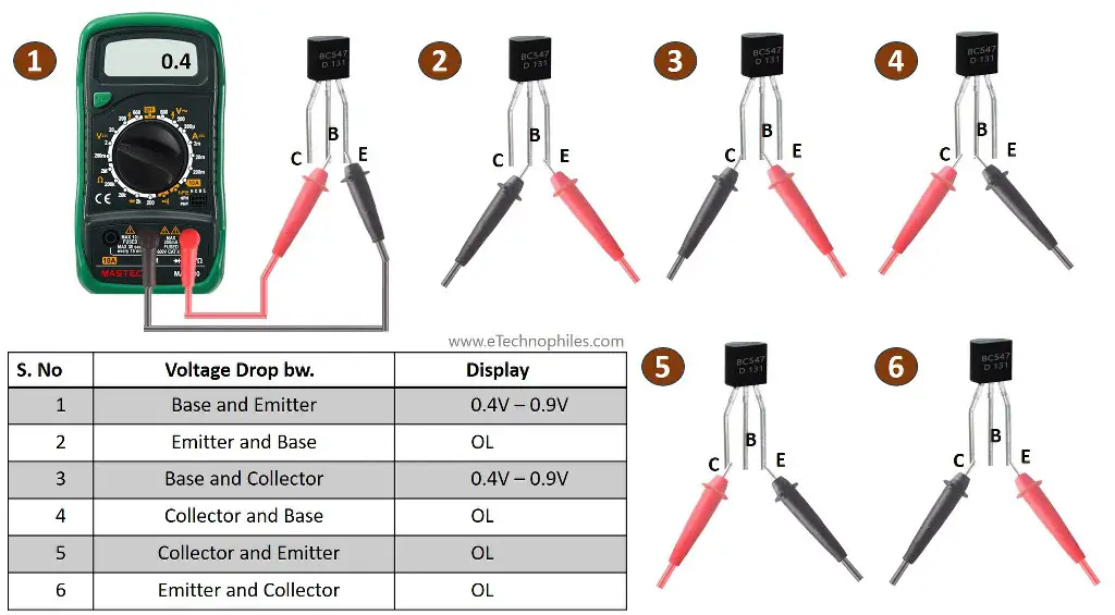
Step 1 - Turn on the digital multimeter and set the rotary switch to diode mode.. Step 2 - To test the Base to Emitter of BJT, connect the positive probe (red) to the base terminal of the transistor and the negative probe (black) to the emitter terminal. The diode formed between the base and emitter gets forward bias with this connection, and the meter displays the numerical value. Testing a Transistor with a DMM. A digital multimeter can be used as a fast and simple way to check a transistor for open or shorted junctions. For this test, you can view the transistor as two diodes connected as shown in Below Figure for both npn and pnp transistors. To test an NPN transistor, connect the multimeter's red probe to the transistor's base and the multimeter's black probe to the transistor's emitter. If the transistor is working properly, the multimeter should display a voltage drop of around 0.7 volts. To test a PNP transistor, connect the multimeter's black probe to the transistor's base and