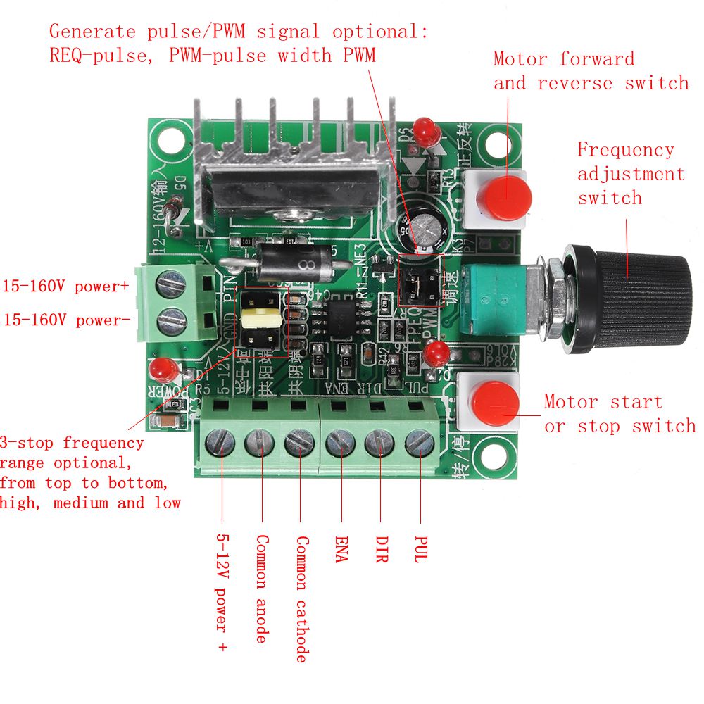
Super simple stepper motor controller Circuit Diagram This non-control is present because of the moment of inertia, For the stepper motor to work properly and non-stop we need a stepper motor controller. So here we design a simple 555 timer stepper motor controller circuit with a few easily available components, it makes the stepper motor drive continuously without any interruption or step stop. Stepper motors are available in several versions and sizes with a variety of operating voltages. The advantage of this general-purpose controller is that is can be used with a wide range of operating voltages, from approximately 5 V to 18 V. It can drive the motor with a peak voltage equal to half the supply voltage, so it can easily handle stepper motors designed for voltages between 2.5 V
Note: Building a Stepper motor driver is more about selecting the proper power supply and driver, and the selection of the micro-controller is secondary. Many micro-controllers can do the simple job of rotating the motor. Still, the design considerations regarding the voltages and currents you must focus on while designing the driver.. Also, a single driver board must handle voltages and

Master Stepper Motors: DIY Driver Circuit Guide (Easy Build!) Circuit Diagram
The goal of this project is to control a 28BYJ-48 unipolar stepper motor using the ULN2003ADR driver IC. We will use an Arduino to generate the control signals, driving the stepper motor to rotate in both clockwise and counterclockwise directions. The motor will rotate in steps, and the speed and direction will be controlled via the Arduino code. The controller we are going to built is based around A4988 stepper motor driver.Its a relatively cheap and can easily be found on any online electronics store.Now before we get into more details have a look at the data sheet of the stepper driver. The driver needs a PWM input on the step pin to operate the motor. Control stepper motors with precision! Build your own driver circuit. This guide simplifies the process with clear explanations, component lists, and step-by-step instructions. A Stepper Motor Driver is a circuit or device that provides the necessary current and voltage to a Stepper Motor so that it has a smooth operation. A Stepper Motor

Built for the Job: The A4988 is specifically designed for bipolar stepper motors like the NEMA 17. It can handle up to 2A per coil (with proper cooling) and works with a wide voltage range of 8V to 35V, making it flexible for most hobby projects and small-scale robotics.; Microstepping Magic: Want smoother, quieter motor operation? The A4988 delivers with 5 microstepping modes (full step, half
Designing a Motor Driver Circuit for a Stepper Motor Using ULN2003ADR Circuit Diagram
Get 10 PCBs for Only $5 (First Order Completely Free) https://www.pcbway.comIn this video I am going to show you how to make a stepper motor controller usin Arduino Stepper Motor Position Control Circuit Diagram and Explanation: The circuit Diagram for the arduino stepper motor control project is shown above. We have used the 28BYJ-48 Stepper motor and the ULN2003 Driver module. To energise the four coils of the stepper motor we are using the digital pins 8,9,10 and 11. The circuit is very simple and inexpensive. This is good thing because most commercial stepper motor controller ICs are quite expensive. This circuit is built from standard components and can easily be adapted to be controlled by a computer. If you use cheap surplus transistors and stepper motor, the price of the circuit can be kept to under $10.