Super Simple Electrocardiogram ECG Circuit 11 Steps with Pictures Circuit Diagram AD8232 ECG Module. By acquiring an electrocardiogram, or ECG, the AD8232 module enables the recording of the electrical activity of the heart. Because electrical signals are transferred through certain routes in the heart and result in the heartbeat, ECG sensors pick up signals from heartbeats.
By understanding the principles of PPG sensing and carefully selecting the appropriate components, you can create a functional and reliable heart rate monitoring system. Remember to prioritize user safety, adhere to best practices in circuit design, and validate your results against established benchmarks.
ECG Monitoring system using AD8232 with Arduino or ESP32 IOT Based Circuit Diagram
So, in today's article, we will go over a step-by-step process on how to design a Heart rate monitor using LM358 Op-Amp IC. This heart rate monitor circuit functions on the principle of photographically: The change in the volume of blood in any organ causes a change in the light intensity through that organ. Here, A Light from an LED will be Features of AD8232 ECG sensor and its working principle. The AD8232 module allows recording the electrical activity of the heart, by obtaining an electrocardiogram or ECG. ECG sensor obtain signals from heart beats because electrical signals are transmitted through specific pathways within the heart, causing the heartbeat. This electrical The ECG was first developed in 1887 and gave physicians a new way to diagnose heart complications. ECGs can detect heart rhythm, heart rate, heart attacks, inadequate blood and oxygen supply to the heart, and structural abnormalities. Using simple circuit design, an ECG can be made that could monitor all of these things.
ECG's are notoriously noisy. This is because you are measuring muscle activation. The furtherthe sensor pads are from the heart, the more muscle noise you will see. These are commonly referred to as "Motion Artifacts". So here are some simple tips to improve the signal quality. Keep sensor pads as close to the heart as you can. Next, you want to create a block diagram in LabView that simulates an ECG signal through an A/D converter and then plots the signal on the computer. We began by setting the parameters of our DAQ board signal by determining what average heart rate we were expecting; we chose 60 beats per minute.

How to Build an ECG and Heart Rate Digital Monitor Circuit Diagram
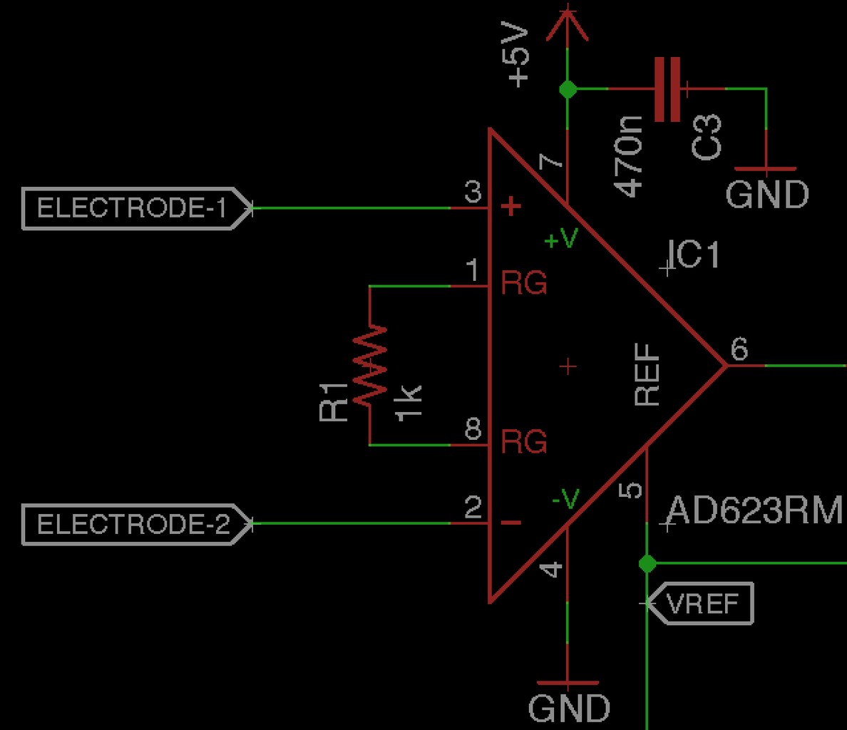
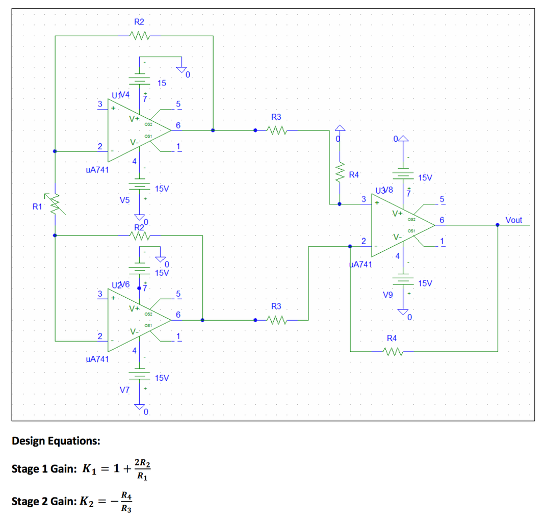
The Figure 3 depicts the circuit diagram of the ECG monitoring and Heart rate measurement system. Fig 3: Designed Circuit diagram of the system A. Design of Instrumentation Amplifier An instrumentation amplifier is usually the very first stage in an instrumentation system. This is because of the very Introduction. A heart rate monitor is a device that measures your heart rate, or pulse, usually in beats per minute (BPM).There are many different types of heart rate monitors. Some, called electrocardiogram machines (abbreviated ECG or EKG), measure your pulse and detect other information from electrical signals from the heart using electrodes placed on the body. The serial plotter will allow you to observe the ECG signal, with the peaks and troughs of the ECG visible. An example output can be seen below. You can also create an automatic bpm readout in the same Arduino script. You do this by noting the values the highest peak reaches to define an upper and lower threshold.
