Stepper Motor Connection and Wiring Circuit Diagram Here is the circuit diagram of a simple stepper motor controller using only elementary parts. The driver circuit uses, four transistor (SL100) to drive the motor windings, two NOT gates and one XOR gate to decode the two bit control logic to drive the four windings of the motor.
When shopping for a TB6600 stepper motor driver, TB6600 stepper motor driver with Arduino UNO and stepper motor wiring diagram. In this tutorial, we will be connecting the driver in a common cathode configuration. This means that we connect all the negative sides of the control signal connections to ground. Circuit Geeks I2C LCD tutorial; Key learnings: Stepper Motor Driver Definition: A stepper motor driver is defined as a circuit used to drive or run a stepper motor, consisting of a controller, a driver, and motor connections.; Essential Components: Key components include a microcontroller, a driver IC like the ULN2003, and a regulated power supply.; Stepper Motor Controller: The controller must have at least 4 output pins Simple Stepper Motor Driver Circuit Diagram Using 555 Timer Ic. Stepper Motors Code Circuits Construction. Arduino Unipolar Stepper Motor Control Simple Projects. Stepper Motor Generator Eeweb. Hybrid Stepper Motor Working Circuit Diagram Construction Electricalworkbook.

Stepper Motor Circuit Diagram
Circuit Operation. The figure displays the two-stage stepper-motor driver circuit diagram. The 555 timer IC now produces the clock or the square wave, as seen in the circuit diagram. In this case, the clock generation frequency can not be sustained continuously, so the step-motor must have variable rpm.
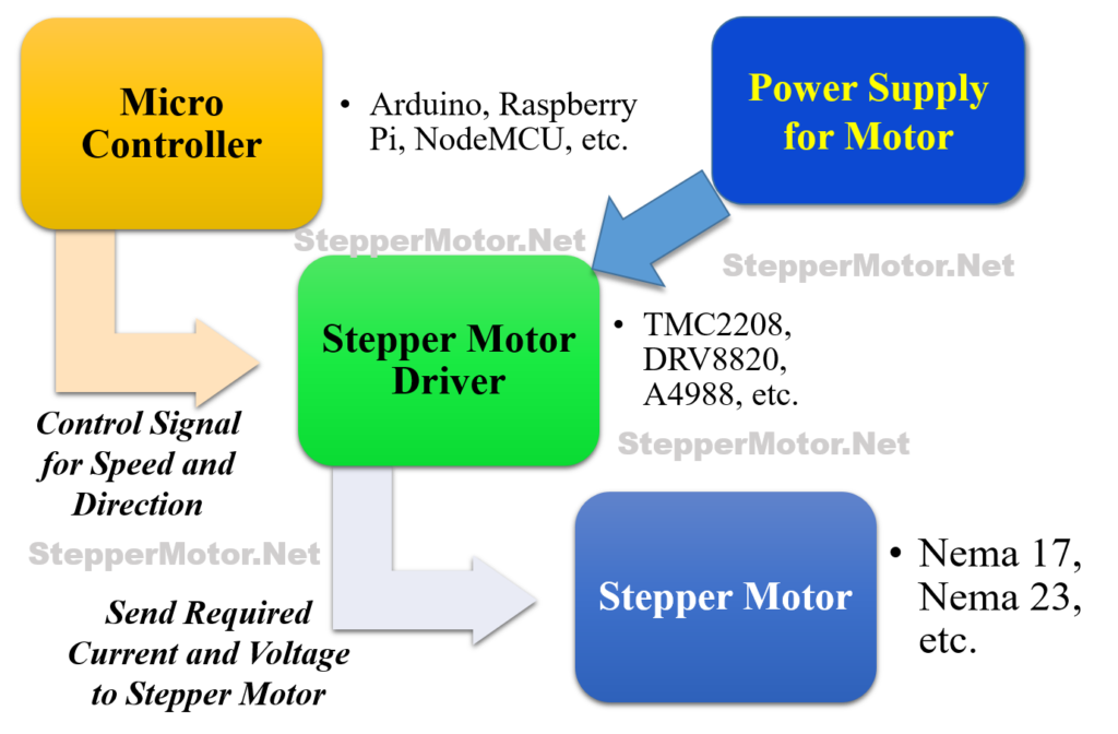
A Stepper Motor Driver is a circuit or device that provides the necessary current and voltage to a Stepper Motor so that it has a smooth operation. A Stepper Motor is a type of DC Motor that rotates in steps. Circuit Diagram. Components Required. 555 Timer IC; CD4017 Johnson Decade Counter (10 Decoded Outputs) 4 x 2N2222 NPN Transistors;

Designing a Motor Driver Circuit for a Stepper Motor Using ULN2003ADR Circuit Diagram
Stepper Motor Driver Circuit Diagram and Explanation. The figure shows the circuit diagram of two stage stepper motor driver. Now as shown in the circuit diagram the 555 circuit here is to generate clock or the square wave. The frequency of clock generation in this case cannot be kept constant so we need to get variable speed for the stepper motor. Learn how to control a stepper motor with the A4988 driver and Arduino. See wiring diagram, current limit settings, example codes and AccelStepper library. The circuit diagram has a two-stage stepper motor driver. Here the timer IC 555 works as an astable multivibrator to generate a clock or a square wave. And produced a square pulse based on the timing resistor and timing capacitor.