Sound Activated Light Circuit Diagram Sound Reactive LED Strip: THERE MAY BE 9 STEPS BUT I PROMISE THIS ONE IS QUICK AND EASY! In this Instructable I will be showing you how to create a light reactive LED system. In this clip, I used a single color LED strip, but you you can use a single LED, multiple LED…
Common Issues and Solutions. If your Arduino Sound Sensor isn't working, try this: LED not responding: Ensure the LED is correctly placed according to its polarity and that all connections are secure.; No reaction to sound: Adjust the sensitivity of the sound sensor, if possible, or check the connections to pin 2.; Conclusion. You now have a sound-activated LED switch!

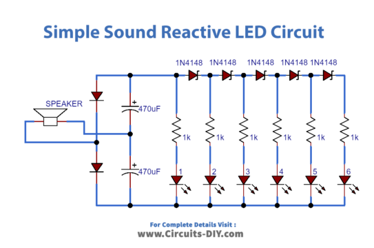
How To Make Simple Sound Activated LED Lights Circuit Diagram
In this video, We'll teach you making a simple sound activated LED light circuit, that circuit led light with dance with the music. You can use this sound re In this video, we are going to show you making a music activated led light circuit without mic and IC. You can make this circuit at home easily. You also can digitalRead(soundSensor); reads the digital value from the sound sensor (either 0 or 1). Serial.print() and Serial.println() print the sound sensor's value to the Serial Monitor. digitalWrite() sets the LED states: If soundValue == 1 (sound detected), all LEDs turn ON. If soundValue == 0 (no sound detected), all LEDs turn OFF.

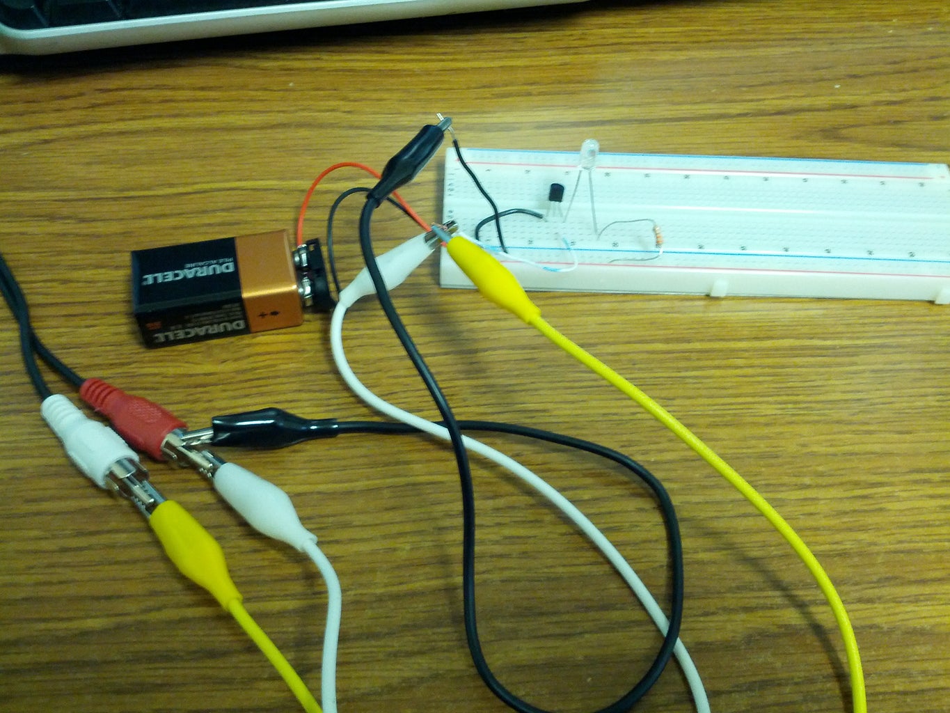
Assembling an electronic DIY Kit "Voice-Activated LED" for beginners.This video shows how to make a Sound Activated LEDs using an electronic DIY kit. The cir Create an immersive audiovisual experience with our DIY Music Reactive LED system, synchronizing aptivating light displays with the rhythm of your favorite music using Arduino. // Analog pin connected to the sound sensor 2 const int ledPins [] = Circuit Diagram. This will help you to Connect all wires. Circuit.png. Code. Code. Code.ino
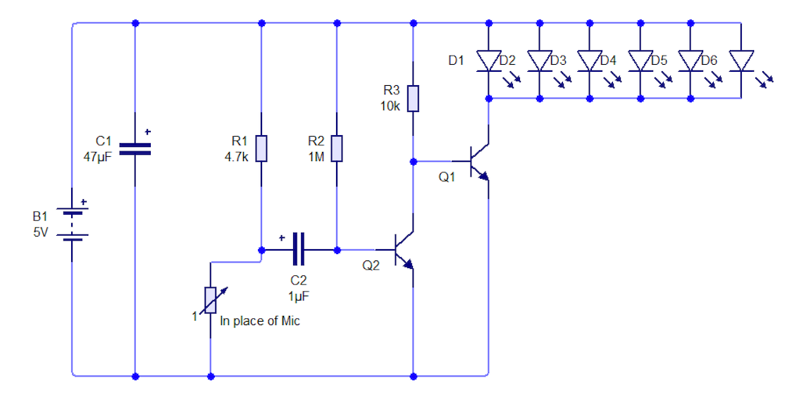
DIY Sound Activated LEDs Circuit Diagram
resistance(R) = (power supply voltage - LED voltage drop) / LED current The typical recommended LED current is 20mA, our power supply voltage is 9V, and the LED voltage drop for a clear blue LED is 3.0V. This results in: (9-3)/0.020=300 ohm Of course this doesn't need to be exact, a 330 ohm resistor will work fine here.

The IC can likewise be utilized to make a good-quality sound detector or sensor circuit. The circuit will blink an LED on any sound like a whistle, clap, human voice, sound system, or cellphone ring when the circuit is close to the mobile phone. As soon as the power is switched on, the microphone is powered. When it responds to sound, it emits an electrical signal. This signal is coupled by capacitor to the first transistor amplification. The amplified signals are sent to second transistor base. Second transistor drives LED to emit light. The louder the sound, the brighter the LED.