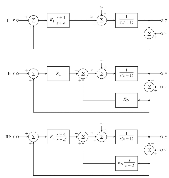
Solved Three alternative feedback control designs are shown Circuit Diagram Let us begin our foray into the world of control systems by considering the frequency control system of Figure 2.1. Such a diagram could represent the tuning input of a voltage-controlled oscillator (VCO), laser, or motor (in which case we'd think of frequency as rotation rate or speed). The system to be controlled is often called the plant. How to Design a Feedback Control System Abstract: This chapter contains sections titled: Intuitive Description of a Control System. Review of Control System Operation. Performance of Control Systems. First-Order Control System Design. Second-Order Control System Design. Circuit Realization of a Second-Order Control System. First-Order Discrete This example shows how to model a feedback control system using Simulink® signals that carry matrix and vector representations of different components of the feedback system. In this example, the controller is designed for a buck-boost converter to track a reference voltage signal. Buck-boost converters are extensively used in distributed
Positive feedback control of the op-amp is achieved by applying a small part of the output voltage signal at Vout back to the non-inverting ( + ) input terminal via the feedback resistor, R F.. If the input voltage Vin is positive, the op-amp amplifies this positive signal and the output becomes more positive. Some of this output voltage is returned back to the input by the feedback network. The symbol used to represent a summing point in closed-loop systems block-diagram is that of a circle with two crossed lines as shown. The summing point can either add signals together in which a Plus ( + ) symbol is used showing the device to be a "summer" (used for positive feedback), or it can subtract signals from each other in which case a Minus ( − ) symbol is used showing that the this control system using only core independent peripherals with some external resistors and capacitors. By combining the voltage regulation of a system with the microcontroller, the cost of the system, as well as complexity, can be reduced by eliminating the need for a dedicated controller IC. The controller also adds the ability to adjust the
How to Design a Feedback Control System Circuit Diagram
6 Practical Feedback Loop Analysis for Voltage-Mode Boost Converter . Figure 5. Effect of Input Voltage Variation on the Control Characteristicof the Boost Converter More equations are created when the boost converter operates in discontinuous-conduction mode (DCM). When this happens, the double pole of the LC filter is heavily damped, and the Design of State Variable Feedback Systems This chapter deals with the design of controllers utilizing state feedback. We will consider three major subjects: Controllability and observability and then the procedure for determining an optimal control system. Ackermann's formula can be used to determine the state variable feedback gain matrix to There are two main types of feedback control systems: negative feedback and pos-itive feedback. In a positive feedback control system the setpoint and output values are added. In a negative feedback control the setpoint and output values are subtracted. As a rule negative feedback systems are more stable than positive feedback systems. Negative