SOLVED An electrical system is to be designed using a feedback control Circuit Diagram this control system using only core independent peripherals with some external resistors and capacitors. By combining the voltage regulation of a system with the microcontroller, the cost of the system, as well as complexity, can be reduced by eliminating the need for a dedicated controller IC. The controller also adds the ability to adjust the
Positive feedback control of the op-amp is achieved by applying a small part of the output voltage signal at Vout back to the non-inverting ( + ) input terminal via the feedback resistor, R F.. If the input voltage Vin is positive, the op-amp amplifies this positive signal and the output becomes more positive. Some of this output voltage is returned back to the input by the feedback network.

Model Feedback Control System Circuit Diagram
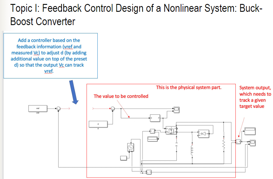
This example shows how to model a feedback control system using Simulink® signals that carry matrix and vector representations of different components of the feedback system. In this example, the controller is designed for a buck-boost converter to track a reference voltage signal. Buck-boost converters are extensively used in distributed How to Design a Feedback Control System Abstract: This chapter contains sections titled: Intuitive Description of a Control System. Review of Control System Operation. Performance of Control Systems. First-Order Control System Design. Second-Order Control System Design. Circuit Realization of a Second-Order Control System. First-Order Discrete
Design of State Variable Feedback Systems This chapter deals with the design of controllers utilizing state feedback. We will consider three major subjects: Controllability and observability and then the procedure for determining an optimal control system. Ackermann's formula can be used to determine the state variable feedback gain matrix to There are two main types of feedback control systems: negative feedback and pos-itive feedback. In a positive feedback control system the setpoint and output values are added. In a negative feedback control the setpoint and output values are subtracted. As a rule negative feedback systems are more stable than positive feedback systems. Negative
PDF 8. Feedback Control Systems Circuit Diagram
The symbol used to represent a summing point in closed-loop systems block-diagram is that of a circle with two crossed lines as shown. The summing point can either add signals together in which a Plus ( + ) symbol is used showing the device to be a "summer" (used for positive feedback), or it can subtract signals from each other in which case a Minus ( − ) symbol is used showing that the