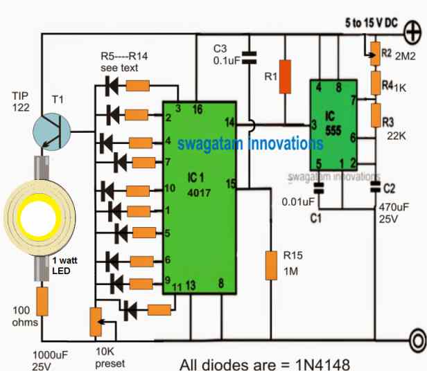
Simple LED indicator light Circuit Diagram Simple 6 Watt SMPS LED Driver Circuit. The following design depicts a simple 6 watt driver example using a cheap commercial SMPS board. Simply by adding a current controller stage between the SMPS and the LEDs, we transform the SMPS circuit into a fully compatible LED driver module for the 6 watt LEDs. Parts List. T1 = TIP122. T2 = 2N2222
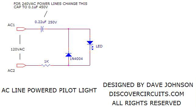
2) LED as a Continuity tester: The above shown circuit is LED as continuity tester. This circuit is used for checking continuity of cables, connectors and switches. When A and B terminals are shorted, the LED glows due to battery connected inside indicating the presence of continuity. 3) LED as a High a.c voltage indicator:
Step Guide: How to Make a Simple LED Circuit Diagram
LED indicators are crucial components in various electronic projects. They provide visual feedback on the status of a circuit or system. In this blog post, we'll explore how to create a simple LED indicator using a 555 timer IC. The circuit is built around the 555 timer IC, which is configured in astable mode to generate a square wave output. Smallest LED Flasher. Flashing LED indicator look very attractive but the design can be more interesting if the circuit uses the least number of parts. The following circuit shows how a single LED can be configured with a single transistor to create a reliable flashing LED indicator. For more information about this circuit you can refer this Learn how to create a simple LED circuit diagram. This article provides step-by-step instructions for building a basic LED circuit. displays, and indicators. The basic components in an LED circuit diagram include the LED itself, a power source (such as a battery or power supply), resistors, and wires. The LED must be connected in the
The current will flow from the battery through the resistor and LED and then back to the battery. The resistor and LED are connected in series, which means one after the other. In this way, the resistor limits the current flowing in the whole circuit, regardless of whether it comes before or after the LED in the circuit. Simple Basic LED Circuit. Step 1: 3 Volt Basic LED Circuit With 10 Ohms Resistor. The above diagram shows a 3V LED circuit, in this circuit there are two AA cells are used. When you are operating an LED with 3V you have to use minimum 10 ohms resistor . Again, my LED is 1.7V, it takes 20mA (which is .02 A) of current and my supply is 4.5V. So the math is R = (4.5V - 1.7V) / .02 A R = 140 ohms Once I knew that I needed a resistor of 140 ohms to get the correct amount of voltage to the LED I looked into my assortment package of resistors to see if I could find the right one.
LEDs for Beginners : 9 Steps (with Pictures) Circuit Diagram
In this video, learn how to create a simple 220V LED indicator circuit using just a few components. This DIY project is perfect for beginners and requires mi Circuit 5# Battery voltage level indicator circuit. This circuit is simple battery level indicator circuit. Which be simple complicated can see that the circuit has will LED keep for display arrive at 3 step. The work of the circuit be this circuit was fixed come to give a temple volt usual that about 11V-14V.
