Shift Register Circuit Diagram The circuitry also differs in that the shift register is not directly driving the led's, instead the shift register outputs are sent through a 1Kohm resistor to the base of a NpN transistor, when the output of the bit is high, it lets enough current and voltage pass into the transistor to switch the connection tween the collector and emitter Bit 0 in the shift register accepts the current value on the DATA pin. On the rising edge of the clock pulse, if the DATA pin is high, 1 is pushed into the shift register, otherwise 0. This process will continue as long as 74HC595 is clocked. When the latch pin is enabled, the contents of the shift register are copied to the storage/latch register.

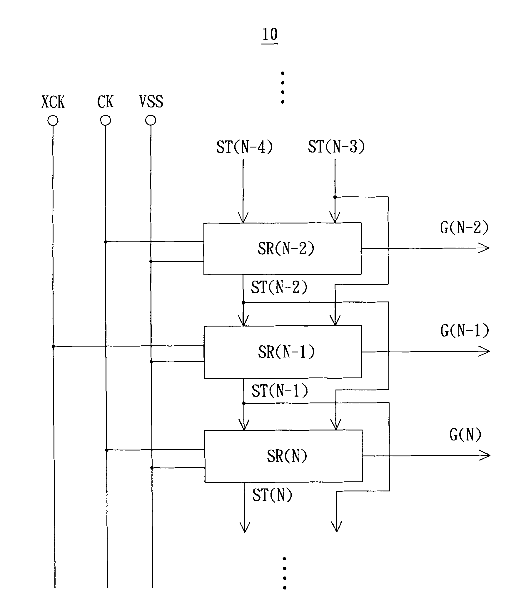
Serial in - serial out (SISO) shift registers. The following circuit shows the structure of a serial in - serial out shift register made with D flip-flops: This shift register accepts just one bit of data at the serial data input. It will move sideways to the next D flip-flop every time the Clk input receives a valid trigger signal. Shift registers come in two main types, a SIPO (Serial-In-Parallel-Out) or PISO (Parallel-In-Serial-Out). The standard SIPO chip is a 74HC595 shift register, and the PISO chip is a 74HC165 shift register. A SIPO is useful for driving a large number of outputs, like LEDs, or 7 segment displays, and a PISO is useful for gathering a large number A microprocessor communicates with a shift register using serial information, and the shift register gathers or outputs information in a parallel (multi-pin) format. or a digital transistor circuit. If you are testing them, it's recommended to just directly tie them to power or ground to make sure everything is working correctly. For the
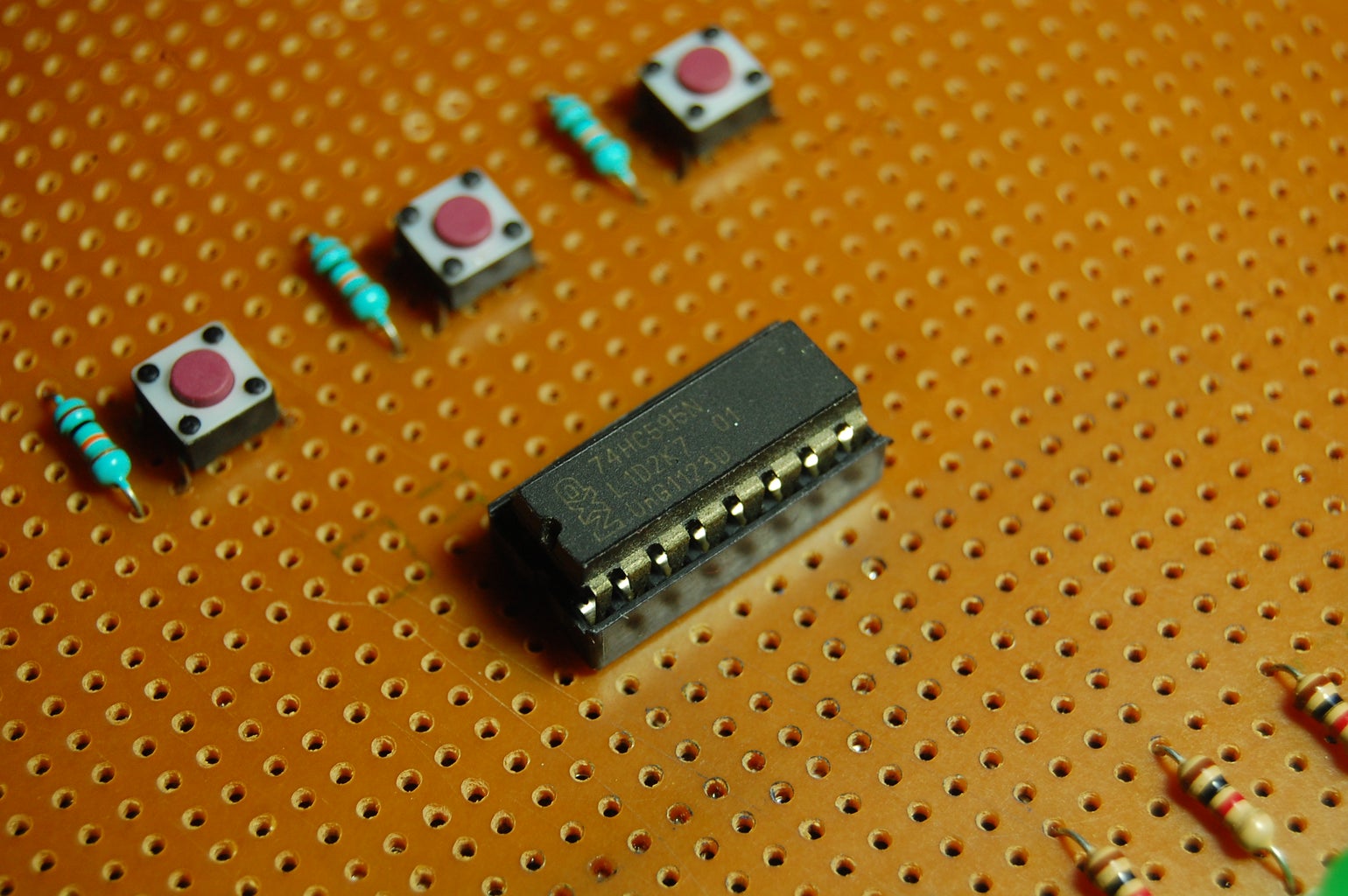
Shift Registers Circuit Diagram
The Shift Register is another type of sequential logic circuit that can be used for the storage or the transfer of binary data. A simple Shift Register can be made using only D-type flip-Flops, one flip-Flop for each data bit. The output from each flip-Flop is connected to the D input of the flip-flop at its right. The shift register, which allows serial input (one bit after the other through a single data line) and produces a parallel output is known as the Serial-In Parallel-Out shift register. The logic circuit given below shows a serial-in-parallel-out shift register. The circuit consists of four D flip-flops which are connected. Shift registers are devices that are quite popular when using micro controllers as they can be used to expand the number of inputs or outputs available. In t
In this tutorial you will learn how to use a shift register (or serial to paralled controller). The shift register will give to your Arduino an additional 8 digital outputs, by using only 3 pins on your board. In this tutorial you will practice by using the shift register with Arduino uno to control 8 LEDs. So, let's get started!