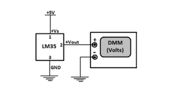
Schematic of the experimental setup for the remote contactless Circuit Diagram 📱 Build a Contactless Smart Thermometer! 🔧🤖 Discover how to make a contactless smart thermometer using the MLX90615 IR temperature sensor, Arduino, and A This simple Arduino project can be used to monitor your own temperature every morning or used in public places as contact less thermometer. Contactless Thermometer. circuit diagram. circuit diagram. circuit diagram. circuit diagram. Comments.

In the above prototype circuit of a contactless IR thermometer circuit, we find the thermopile sensor IC MLX90247 in the bipolar mode, configured with an external op amp designed to amplify tiny electrical from the thermopile into a measurable output. A simple differential VU meter is attached across the outputs of the two op amps. As long

IR Thermometer With Medical Application (Contactless) Circuit Diagram
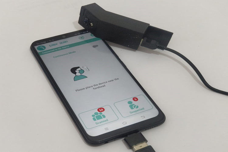
The working principle is very simple, the infrared thermometer sensor MLX90614 reads the human body temperature when the distance ( measured by IR sensor ) between the forehead and the sensor matches a set value. After making the circuit, I realized that the wiring connection is really messy. To make the wiring cleaner and simpler, I have MLX90614 with ESP8266 Nodemcu: MLX90614 with ESP8266 Nodemcu & Blynk, IoT Temperature Sensor- In this article, you will learn how to make IoT temperature monitoring system using MLX90614 contactless infrared temperature sensor, Nodemcu ESP8266 WIFI module, SSD1306 I2C supported Oled display module and Blynk application.. Just don't skip this part of the article, because there are certain Verify temperature readings: Compare the temperature readings from the contactless thermometer with a known reference, such as a calibrated mercury thermometer or a high-quality digital thermometer. If the readings differ significantly, calibrate the MLX90614 sensor as described in the "Calibrating the Thermometer" section.
View the full DIY project article: https://circuitdigest.com/microcontroller-projects/contactless-smart-thermometer-using-mlx90615-ir-temperature-sensor-ardu If your sensor is not on breakout board gonna need to pull-up the SDA and SCL pins of it, the put a capacitor between the GND and +3.3v pins. If its on breakout board then just connect the pins to the Arduino board, SDA with A5 and SCL with A4, GND to GND and +3.3 to 3.3v. To operate the IR thermometer, you need to continuously press the longest button (the one we soldered to pin D5 of the arduino), bring the thermometer close to an obstacle and when the thermometer is close enough, it will beep and take the temperature. You can change the mode (medical or object) by pressing the other button for about 3s.