Radio Transmitter Diagram Circuit Diagram How the FM Transmitter Works. The circuit is powered by a 9V power supply.Transistor Q1 is a high gain audio amplifier that amplifies the sound detected by the electret microphone.The output of Q1 is fed into the frequency modulating circuit created by transistor Q2, inductor L1, and variable capacitor C5.. This is a very high frequency (VHF) circuit, so you will want to use transistors with a Although the circuits used in radio stations for AM broadcasting are far more complicated, this nevertheless gives a basic idea of the concept behind a broadcast transmitter. Plus it is a lot of fun when you actually have it working! Before we get into the step-by-step instructions for building the circuit, we'll first go over the circuit design. A FM transmitter is a device that uses the principles of frequency modulation to broadcast sound supplied at its input. Typical FM transmitter design's usually follow the block diagram below; The signal strength of audio inputs into the transmitter is usually low therefore an amplifier is usually built to bring the signal level up.
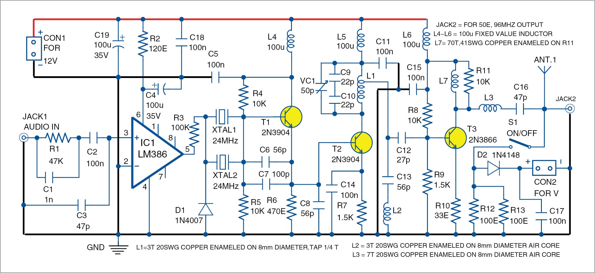
Here we'll discuss how to build small FM transmitter circuits using 10 different methods, one that consists of wire link from the transmitter to the receiver, and the other which is completely wireless and can be used to eavesdrop a particular conversation over a range of about 30 meters, over an ordinary FM radio. All the FM transmitter It serves as a visual guide for engineers and enthusiasts who are designing or troubleshooting radio transmitters. Understanding the essential components of a radio transmitter circuit diagram is important for building a functional and efficient transmitter. 1. Oscillator. At the heart of a radio transmitter circuit diagram is an oscillator.
Make Your Own Low-Power AM Radio Transmitter Circuit Diagram
Building a simple transmitter and receiver is the quickest way to get started on your journey into the world of RF. It is also a lot of fun. This tutorial provides an excellent introduction to building a simple digital communication system. Martyn Davies provides a good overview of modulation, RF circuits and programming with an Arduino.

The term RF stands for "radio frequency" and the RF transceiver module will always work in pairs because it needs a transmitter and a receiver to send and receive data. The transmitter can only send information and the receiver can only receive information, so data can always be sent from one end to the other, not the other way around.
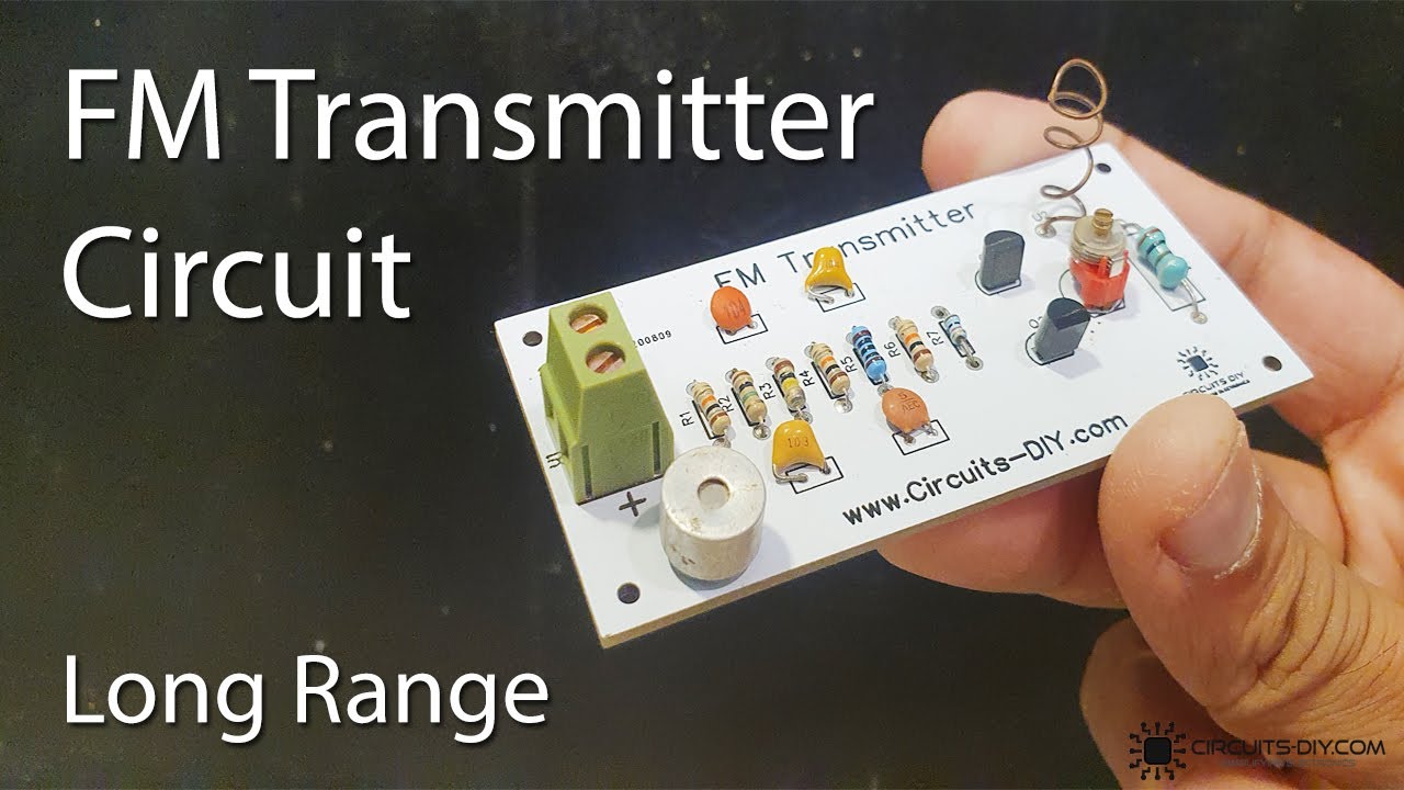
How to Build an FM Transmitter Circuit Diagram
With this circuit, you will be able to transmit your voice over short distances using basic components. Building your own FM transmitter is a great way to experiment with electronics and learn more about how radio frequency works. This circuit is perfect for electronics hobbyists with some circuit experience from before. The Circuit Building AM and FM radio receivers and transmitters is a fun way to explore concepts like electromagnetic waves, resonance, filters, and audio amplification. The projects can be used in a home audio system or made portable with battery power. The following components are required to make FM Transmitter Circuit. S.no Component Value Qty; 1. Antenna: we are going to design a Simple Doorbell circuit using a 555 Timer IC. It is a very common and useful device. Almost everyone uses it. FM transmitter is a low-power FM radio transmitter that communicates Read more Read more.
