Power On Delay Circuit Diagram Most of the time we don't want certain circuits or electronic devices to turn on immediately, in those scenarios we need a delay circuit to provide a few seconds delay before powering on our appliances. In this project, we are going to make a Power ON delay timer circuit using 555 timer IC which is an ideal circuit for these purposes.
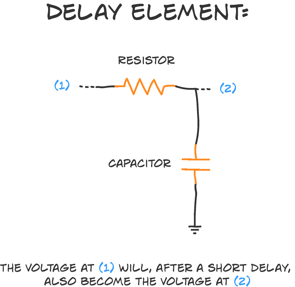
The RC delay element is a way to create a time delay in your circuit by connecting a resistor and a capacitor. It's super simple. And very useful. The 'R' is a resistor, and the 'C' is a capacitor. That's where the 'RC' comes from. And here's how you connect the two: How does it work? A capacitor is kinda like a tiny little Its now time to test the circuit and add the extras. Add a button connecting the positive rail to the signal in line and connect an LED and a resistor to the signal out line. Apply power and push the button, if it lights up for a short time then fades out, the circuit is working properly and you can now add the relay if you do so choose. Using a Start Push-Button. The above design could be upgraded with a push-button to facilitate a push button start. This further ensures that the timer shuts off completely in case a power failure occurs while the circuit is operational, which in turn ensures that crucial loads like heater, or geyser are completely turned OFF during such situations.

Build Electronic Circuits Circuit Diagram
In this video, I will explain the working of the transistor timer circuit, also known as delay timer or turn on circuit, which is an example of a hobby elect TIME DELAY SWITCH CIRCUIT: Have you ever wanted to delay the time ,of which an electric gadget at home,office and industry performs its function.This simple circuit,provides a solution. POWER SUPPLY CIRCUIT: The power supply circuit, consist of the 9v source from the battery, the 220uf electrolytic capacitor and the light indicator in A simple power on delay circuit using IC 555 establishes a delay between power supply and circuit activation. When a trigger is received, the IC 555 runs in monostable mode, which causes it to produce a single output pulse for a predetermined amount of time. The timing network that establishes the delay time is made up of the resistor R1 and
In this circuit, we will show how to build a delay before turn on circuit with a 555 timer chip. A delay before turn on circuit is a circuit that once you apply power to it doesn't turn on the output right away. There is a delay before the output turns on. For this circuit, it's a few seconds delay. Once these few seconds pass, then the output

Power ON Delay Using 555 Timer IC Circuit Diagram
This simple delay timer circuit is used to prevent noise and spike in electrical equipment before switching on the main input supply. Most electrical appliances powered by 230V AC mains produce large voltage spikes when the power is switched on. The voltage spike also affects low-power electronic circuits.