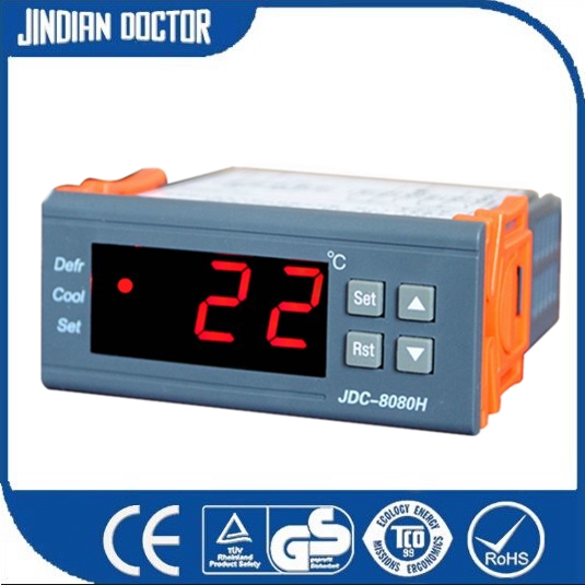
Microcomputer temperature controller Circuit Diagram The Automatic Temperature Control System continuously monitors the ambient temperature using a sensor and compares it with a set point temperature defined by the user. If the measured temperature deviates from the set point, the microcontroller activates heating or cooling devices through a relay module to bring the temperature back to the

In this video, you will learn how to design and build a temperature monitoring system using the PIC16F877A microcontroller, simulated in the Proteus software obtained from the sensor are analysed using MATLAB. Index terms -Microcontroller, Temperature Sensor, LCD, Measurement and Control, ATMega 328, LM35 I.INTRODUCTION The temperature monitoring and controlling system is an integrated device that allow users to input specific requirement of temperature for any environment say any industrial process. In this tutorial, we are making a Digital Thermometer using PIC microcontroller and LM35 Temperature Sensor. In this project, we will sense the temperature using LM35 and display it on 16×2 LCD. LM35 Temperature Sensor is accurate and cheaper and doesn't require any external calibration.

Temperature sensor using PIC16F877A microcontroller Circuit Diagram
The circuit diagram illustrates how the components, including the PIC16F877A microcontroller, LM35 temperature sensor, and LCD display, are interconnected to form a complete temperature measurement system. By using the microcontroller's analog-to-digital converter (ADC) to read the voltage from the LM35 temperature sensor and utilizing 5. Circuit Design and Wiring. Connect the DHT11 sensor data pin to RB0 of the PIC16F877A.The LCD module is connected in 4-bit mode, using pins RD0, RD1, RD2, RD4, RD5, RD6, and RD7.The 10K potentiometer is used to adjust the contrast of the LCD. A 4 MHz crystal oscillator is connected between OSC1 and OSC2 of the microcontroller, along with two 22pF capacitors to stabilize the clock. This project demonstrates how to design a temperature monitoring system using a PIC microcontroller, a temperature sensor (LM35), and a 16×2 LCD display. The system measures temperature in real-time and displays it on the LCD. It can be used in applications like environmental monitoring, industrial temperature control, and home automation systems.

Microcontroller-Based Temperature Monitoring and Control is an essential and practical guide for all engineers involved in the use of microcontrollers in measurement and control systems. The book provides design principles and application case studies backed up with sufficient control theory and electronics to develop your own systems. It will In this tutorial, we'll discuss how to interface the LM35 temperature sensor with a PIC microcontroller. Using the ADC to get the analog output voltage of the sensor then converting it back to Celsius degrees, and finally display the result on an LCD and also send it via serial port to a host PC to monitor the temperature remotely. Accurate Temperature Measurement Using an NTC Thermistor with an Arduino or STM32 Microcontroller In this blog post, we will explain how to design a circuit to directly monitor temperature using an NTC thermistor with an analog-to-digital (ADC) converter on any microcontroller like an Arduino or STM32.
