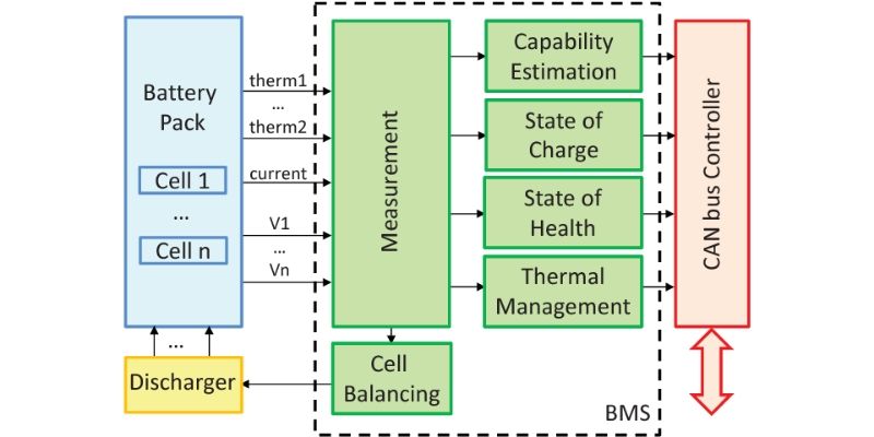
Live Webinar Designing Battery Systems with Modeling and Simulation Circuit Diagram Figure 1: BMS Architecture. The AFE provides the MCU and fuel gauge with voltage, temperature, and current readings from the battery. Since the AFE is physically closest to the battery, it is recommended that the AFE also controls the circuit breakers, which disconnect the battery from the rest of the system if any faults are triggered. Introduction A battery management system (BMS) is an electronic system that manages a rechargeable battery pack. Its main functions are to monitor the battery's state, calculate secondary data, report that data, control its environment, authenticate and balance the individual cells and protect the battery. A good BMS is crucial for extracting maximum performance from a […] This is where a Battery Management System (BMS) becomes crucial. A well-designed BMS circuit can prevent overcharging, over-discharging, and short circuits, while also balancing individual cells in a battery pack. ensuring that the charging process is safe and consistent for the entire battery pack. Circuit Design for 3S Configuration 1.
Learn the high-level basics of what role battery management systems (BMSs) play in power design and what components are necessary for their basic functions. Nowadays, Li-ion batteries reign supreme, with energy densities up to 265 Wh/kg.

How to Design a Good Battery Management System (BMS ... Circuit Diagram
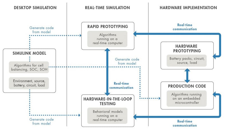
connecting the battery system to the power source and load. Simscape Electrical, an add-on product for Simulink, provides complete libraries of the active and passive electrical components needed to assemble a complete battery system circuit, such as the analog front end for cell balancing. The charging source can consist of a DC supply, such
When designing a BMS, it is important to consider where the battery protection circuit-breakers are placed. Generally, these circuits are implemented with N-channel MOSFETs since they have a lower ARTICLE - HOW TO DESIGN A BATTERY MANAGEMENT SYSTEM (BMS) Article #0082 Rev. 1.0 MonolithicPower.com 5 8/1/2022 MPS Proprietary Information Improper charging can cause lithium-ion batteries to swell or even explode. Deep discharge can also lead to battery failure. An ideal lithium-ion battery charger should have voltage and current stabilization as well as a balancing system for battery banks. The voltage of a fully charged lithium-ion cell is 4.2 Volts. Future Trends in Battery Management System Circuit Design. In recent years, the development of battery technology has become crucial in various industries, such as electric vehicles, renewable energy systems, and portable devices. The efficiency and performance of these batteries depend significantly on the proper management and control of

Introduction to Battery Management Systems Circuit Diagram
BMS (Battery Management System) is a comprehensive system that includes monitoring, control, and protection functions for battery packs, while a battery protection board typically refers to a simpler circuit that provides basic protection functions such as overcharge and over-discharge protection for individual cells or small battery packs.
