LED Electronic Microcontroller Digital Clock Time Date The Circuit Diagram For this clock, we can set the time at any instant. Here, the clock can work in either 24 hour mode or 12 hour mode and the RTC chip is configured by programming 8051 controller. I will demonstrate two circuits of Digital Clocks using 8051 Microcontroller: one uses the RTC DS12C887 and the other uses the RTC DS1307. Circuit Principle
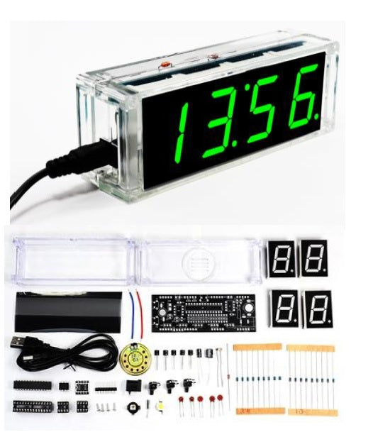
The digital clock circuit uses the 50-60hz oscillation of AC power.Most digital alarm clocks display the hour of the day in the form of 12 hours or 24 hours with an indication of AM or PM. Most digital alarm clocks use LCD display, seven segment display or VFD. Digital clocks run with mains electricity and must be reset the time when the power How to make seven segment digital clock & How to coding or programing in PIC Microcontroller IC or Chip. Get Circuit Diagram of Simple Digital Clock Using PI Here in our demo video we are using proteus simulation but definetly if you are doing it in your hardware you will be required these components for this project: 8051 Development board: So if you have this board it will be better so that you can easily upload the code by yourself.

How to Make a Digital Clock Using 8051 With 7 Segment Display Circuit Diagram
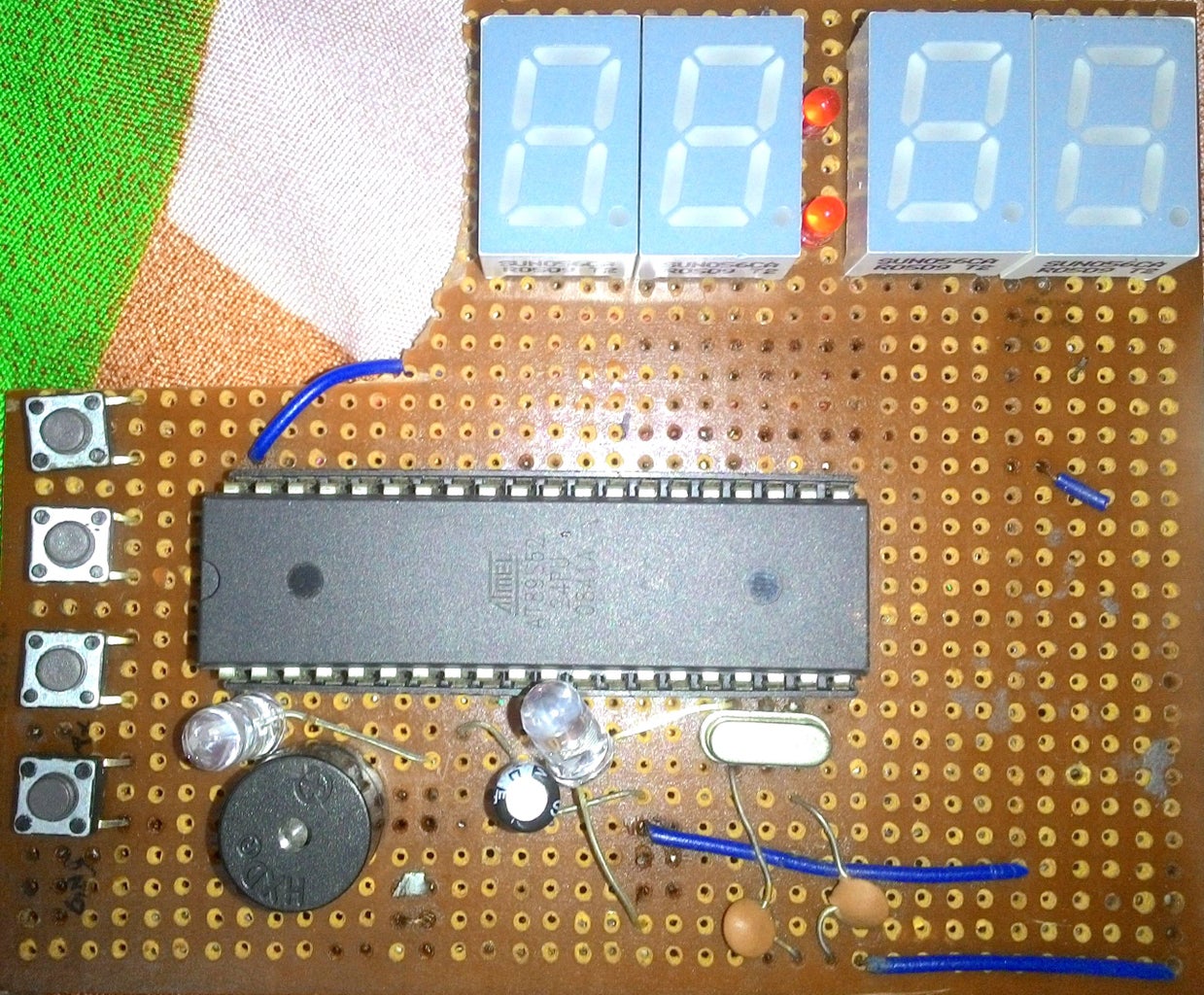
In our previous tutorial, we explored the interfacing of the RTC-DS1307 with a PIC microcontroller PIC16F877A using an LCD display.In this tutorial, we'll take it a step further and create a Digital Clock with a 7-Segment Display (HH:MM format) using the powerful PIC controller, the PIC16F877A.This project involves interfacing a 7-Segment Display and the RTC-DS1307 with the PIC controller. This is the circuit diagram of the digital clock using 8051 microcontroller. As we can see the microcontroller is connected to three 7 segment display with distinct ports not multiplexed and the last hour digit is only connected to a pin as it only shows 1.. LED and buzzer are self explanatory according to the code.. 1 of the LED is for AM and I have connected another LED not shown in the

Real time clock (RTC) is widely used in many application to provide accurate time. This article explains the making of a simple digital clock using RTC DS 12C887 and 8051 microcontroller (AT89C51). The output is displayed on an LCD. This clock also has a provision of setting time at any instant. The clock uses the concept of our earlier articles of interfacing RTC DS12C887 with microcontroller Usually digital RTC(real time clocks) are interfaced with microcontrollers to make a digital clock. But i utilized the internal timers of 89c51 microcontroller to generate a precise time for making a clock with 8051 microcontroller. 16×2 lcd is interfaced with 8051 microcontroller to display time on lcd. Time in minutes, hours and seconds will
![Digital Clock But Without a Microcontroller [Hardcore Electronics] : 14 ... Circuit Diagram](https://content.instructables.com/FUL/XVRV/KFQTVQ57/FULXVRVKFQTVQ57.png?auto=webp&fit=bounds&frame=1&height=1024&width=1024auto=webp&frame=1&height=300)
Make Digital Clock & Learn PIC Microcontroller Programming Circuit Diagram
Circuit diagram of digital clock ds1307 using pic mirocontroller is given below. DS1307 real time clock is interfaced with PIC16F877A microcontroller. Instructions for interfacing real time clocl ds130 is given. 3 volt battery is used as back up which is used in case of main power supply faliure.PIC16F877A microcontroller fetch time and date A digital clock is one that displays time digitally. The circuit explained here displays time with two 'minutes' digits and two 'seconds' digits on four seven [[wysiwyg_imageupload::]]segment displays. The seven segment and switches are interfaced with 8051 microcontroller AT89C51. This circuit can be used in cars, houses, offices etc. As soon as the Vcc supply is provided to this