IR Sensor Circuit Types Working Principle Its Applications Circuit Diagram The IR receiver that I am going to discuss is the normal IR receiver instead of 38kHz IR receiver. IR receiver detects the amount of infrared received and varies the resistance across the receiver. Therefore, we can measure the voltage across the receiver to detect the amount of IR received. IR Sensor Pinout. The IR sensor has a 3-pin connector that interfaces it to the outside world. The connections are as follows: VCC is the power supply pin for the IR sensor which we connect to the 5V pin on the Arduino.. OUT pin is a 5V TTL logic output. LOW indicates no motion is detected; HIGH means motion is detected.
How to use IR Sensor Module with Arduino. We need to connect the IR sensor with Arduino properly to read the output of the sensor. First of all, we connected the sensor Vcc pin to the Arduino 5v pin and the GND pin is connected to the Arduino ground (GND) pin, to activate the IR sensor module. Then connect the sensor output pin to one of the digital pin of Arduino to read the output value from
IR Sensor With Arduino: wiring and code explained Circuit Diagram
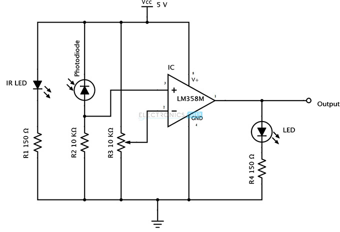
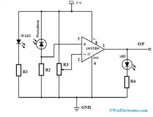
Now you understand how the IR LED and Photodiode works together as a sensor, we are going to transform the previous circuit into an alarm circuit. This circuit will use an OP Amp to Amplify the photodiodes signal, a buzzer is connected to the output of the OP Amp but that can be modified and replaced with another component/circuit. The application circuit of the IR sensor is an obstacle detecting circuit that is shown below. This circuit can be built with a photodiode, IR LED, an Op-Amp, LED & a potentiometer, The main function of an infrared LED is to emit IR light and the photodiode is used to sense the IR light. In this circuit, an operational amplifier is used as a

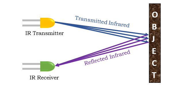
IR Sensor is a device that detects the object in front of it using IR or Infrared waves. It is also used to differentiate between black and white colors. Hence it is commonly used as the main sensor in a line follower robot. Hey guys! Today we are going to learn how to use or how to interface an IR sensor with Arduino. So here is your Beginners Guide To IR Sensor.

IR Sensor : Circuit, Types, Working Principle & Its Applications Circuit Diagram
To make Line Following Robot and detection of object, IR sensor is best to use in such situation . IR Sensor Information. In order to be able to interface IR sensor with Arduino, it is necessary to understand what IR sensor actually is. IR stands for the infrared region. Sensors capable of working with that region of light are IR sensors.
Overview. In this guide, we will explore the interfacing of an IR Sensor Module with an Arduino UNO R4 Minima Board. An IR (Infrared) Sensor Module is a device designed to detect infrared light, commonly used in remote control systems, proximity sensors, and line-following robots.. The IR Sensor Module typically includes an infrared transmitter and receiver. There are several different types of IR receivers, some are stand-alone, and some are mounted on a breakout board. Check the datasheet for your particular IR receiver since the pins might be arranged differently than the HX1838 IR receiver and remote set I am using here. However, all IR receivers will have three pins: signal, ground, and Vcc. This Arduino code is designed to use an IR sensor module to detect objects by reading its output signal. The irPin is assigned to pin 7 on the Arduino, where the sensor's output pin is connected. The ledPin is assigned to pin 13, which controls the built-in LED on the Arduino. This LED shows whether an object has been detected by the sensor.