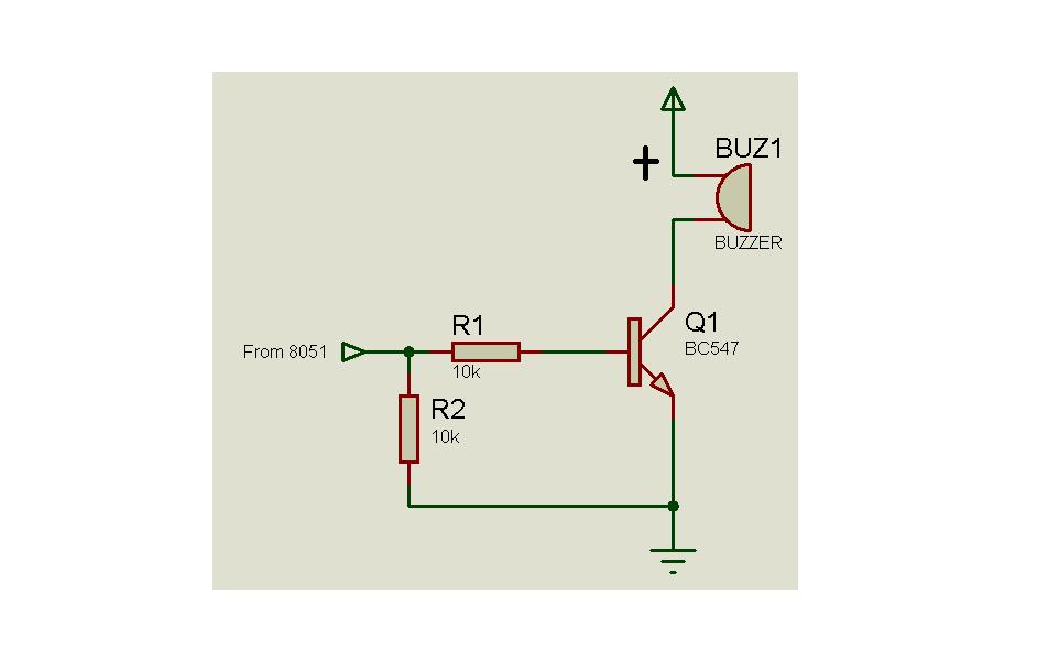
Intelligent Energy Saving System Circuit Diagram Circuit Diagram. Here is a simple circuit diagram for a buzzer circuit: Step-by-Step Instructions. Place the components on the breadboard according to the circuit diagram. Connect the positive terminal of the battery to one end of the pushbutton switch. Connect the other end of the pushbutton switch to the base of the transistor through a 1kΩ
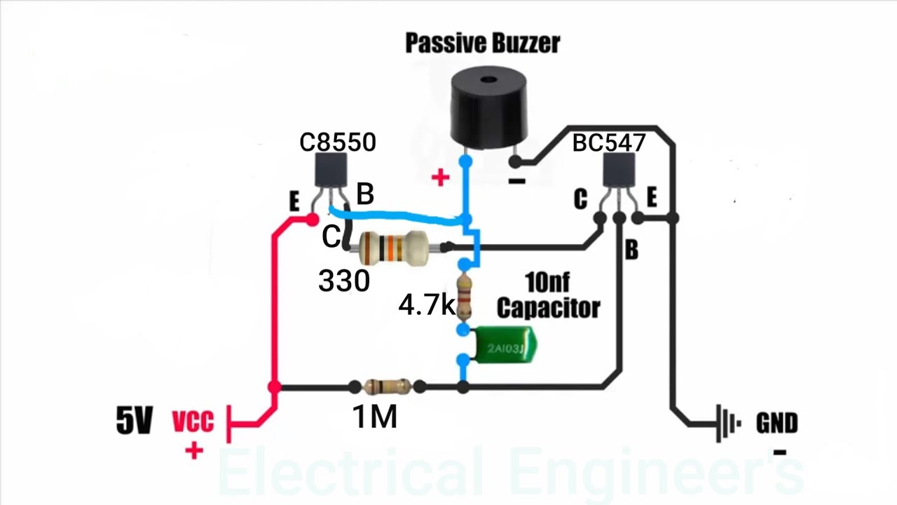
With a few basic supplies and a bit of knowledge about how circuits work, you can quickly make a simple buzzer circuit and start experimenting with the different components to make your own unique buzzing sound. Quiz Buzzer Circuit Using Ic 74ls373 Gadgetronicx. Simple Buzzer Circuit With Ne555 Ic. Simple Piezo Buzzer Circuit With Um66t Ic Figure 1: simple electronic buzzer circuit diagram using two-transistor. By has both resistors- R=1.2K and C=0.047uF to set the output frequency. Which can change slightly the value of both components, so the output sound changed. However, from the experiments, this value will be the best frequency.
Making Simple Buzzer circuit Circuit Diagram
Today I am showing you how to make simple buzzing circuit Buzzer Circuits on a breadboard.I am in no way a expert in electrical engineering but I just wante A buzzer is a high frequency oscillator circuit designed to produce a buzzing sound via a transducer or speaker output. Simple Buzzer using a Single Transistor With just a single transistor, a ferrite inductor, and a piezo transducer, you can create a circuit that will "buzz" or, more accurately, "tweet" for you, potentially producing a
• Simple magnetic buzzer circuit with UM66 IC • Simple Piezo buzzer circuit with UM66T IC • Simple Piezo Buzzer circuit diagram and project details. I feel that the mechanical bell type operation of the alarm could be easily replaced by one of the above circuits; the only problem being that the voltage available is only 1.5V. Simple Buzzer Circuit: The following items are required to build this circuit: 9-Volt Battery Snap 9-Volt Battery Two wires DC Buzzer Breadboard Projects Contests Teachers Simple Buzzer Circuit. By 624117 in Circuits Electronics. 7,039. 1. 2. Introduction: Simple Buzzer Circuit
Simple Buzzer Circuit : 3 Steps Circuit Diagram
The Circuit with all of the values of its resistor and capacitors set, when supplied with 9 Volts of battery, produces a buzzer sound. This IC NE555 drives an 8Ω to 25Ω loudspeaker to produce an audible square-wave tone. In addition to this, a Siren or 555 tone generator can be interchangeably used as a buzzer. Application