How to solder an LED chaser circuit using a few easy steps Circuit Diagram In the next sections we will show how we can create an 18 LED light chaser by linking two of these I Cs together. Cascading Two IC 4017s for the 18 LED Effect Now if we take a look at the circuit diagram for our light chaser, we can see how the two ICs are arranged to allow for the "chasing" or "running" effect across all 18 LEDs. In this Instructable I show you how to make a simple LED chaser circuit. The special thing about this circuit is that it does not use an IC (Integrated Circuit). Video tutorial. By using different resistors, capacitors and transistors, I succeeded in this project to make a circuit that lights the LED lights one by one. The base of both the

7) 100 to 200 LED Reverse Forward Chaser Circuit for Diwali, Christmas Decorations. The 7th concept below explains how to build a simple LED chaser circuit with a push pull or reverse forward sequencing effect. Also, in the later part of the article I have explained how this simple LED chaser could be upgraded to a 100 to 200 LED laser circuit 📌Discover Easy, Affordable, and Reliable PCB manufacturing with JLCPCB! Register to get $60 New customer coupons: https://jlcpcb.com/?from=sritu📌Special De

How to Build an Effective LED Light Chaser Circuit: Step Circuit Diagram
In this article, we will make an LED Chaser Circuit using 555 Timer IC & CD4017. An LED chaser is an electronic circuit that creates a visually appealing effect by sequentially illuminating multiple LEDs, one after the other, in a repeating pattern. This creates the illusion of a "chase" or a "running light" effect, as the illuminated 1. Add LED's on breadboard according to circuit diagram connect all LED negative terminal on negative port of breadboard 2. I add LED in this pattern R G B R G B R G B But you can add LED according to your choice. 3. Now connect jumper cables on the positive side of each LED's 4. Now take arduino and connect 2nd terminals

Working on a led chaser using Arduino. we have made an LED chaser circuit using Arduino and LED. This project is very simple and cost-effective. Components used. These are components used in the LED Chaser circuit project. Arduino; LED (different colors according to your need) Push Button; 5V battery; 220-ohm resistor; Connecting wires

LED Chaser Circuit using 555 Timer IC & CD4017 Circuit Diagram
Circle LED chaser circuit 4017 project. This is one of IC 4017 project that I like it. The Circle LED chaser circuit or 10 LED running light as another kind of string light circuit. Which is running light on circle each one step beautifully and can adjust speed as well. Read also: DIY Flashing Bicycle LED Taillight Circuit. The working principle

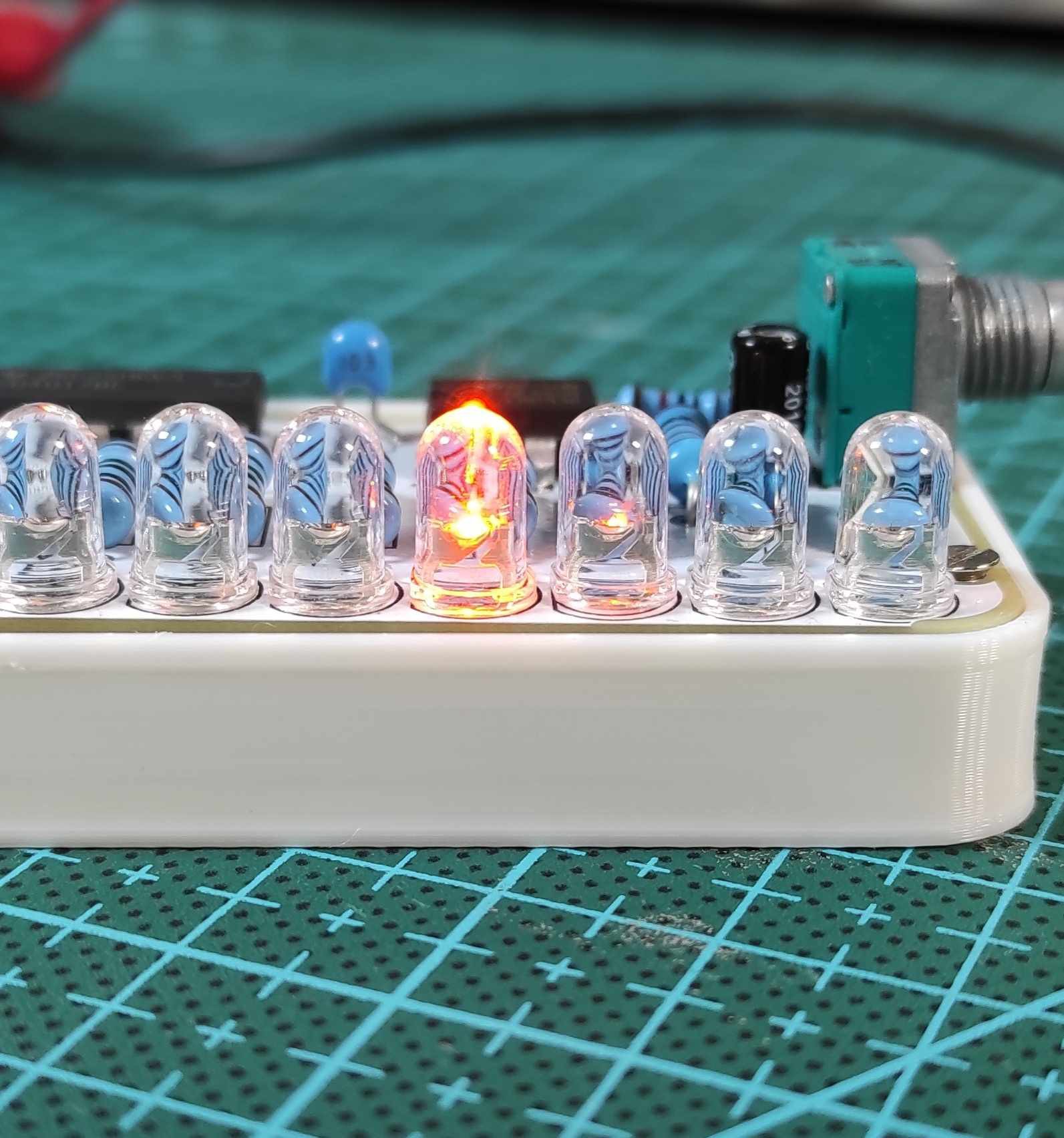
Today I am going to make an LED Chaser circuit without using IC.This circuit is amazing and I will make this circuit using BC547 Transistor.This is Best LED Chaser circuit. Let's get started, Step 1: These Components Required to Make This Project. Components required - (1.) Transistor - BC547 x3 (2.) LED - 3V x6 (3.) Resistor - 560 Ohm x3

How to Make Best LED Chaser Circuit Without IC Circuit Diagram
The LED light chaser circuit is a popular electronic project that creates a sequential lighting pattern using multiple LEDs. This circuit is commonly used in decorative lighting and signage applications to create an eye-catching visual effect. To build a LED light chaser circuit, you will need several components: 1. LEDs: