How to Make a Voltage Multiplier 6 Steps Circuit Diagram In the tutorial about Rectifiers, we saw that the DC output voltage being controlled by the rectifier is at a value below that of the mains input voltage.The Voltage Multiplier, however, is a special type of diode rectifier circuit which can potentially produce an output voltage many times greater than of the applied input voltage.. Although it is usual in electronic circuits to use a voltage DC-DC Voltage Doubler (simplest Possible Circuit): This voltage doubler circuit uses a DPDT switch to alternately charge 2 series connected capacitors. The main purpose of this circuit is to illustrate the principle of operation of switched-capacitor voltage multipliers. Other applications are up t… Welcome to my channel! In this video, I'll show you how to build a voltage multiplier circuit using simple components: capacitors and diodes. Voltage multipl

In this video, I explain the how a Dickson charge pump operates and how to build a basic example.Support these videos on Patreon: https://www.patreon.com/ben

DC Voltage Doubler (simplest Possible Circuit) Circuit Diagram
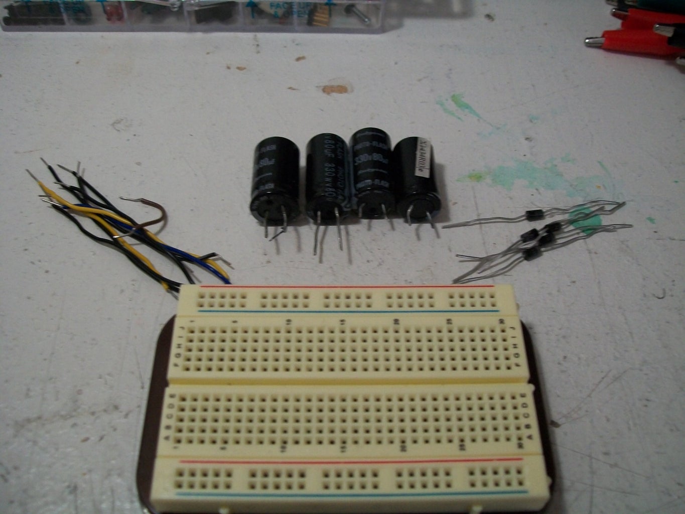
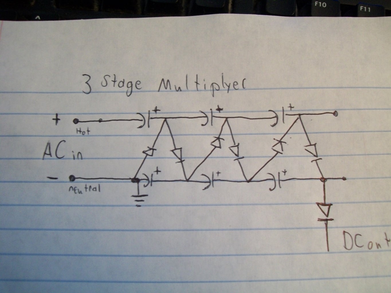
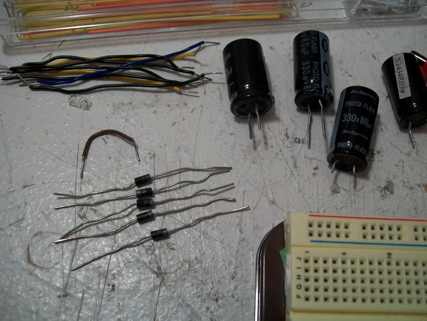
Here is some info about voltage multipliers if you want to know how they work. If not, then skip to the parts list. Definition - "A voltage multiplier is an electrical circuit that converts AC electrical power from a lower voltage to a higher DC voltage by means of capacitors and diodes combined into a network." - Wikipedia

The schematics above will output a positive DC voltage relative to the ground (GND). If a negative output is required then the polarity of the diodes should be reversed. you can learn more about how a voltage multiplier works, by visiting the voltage multiplier page. For safety and improved performance the voltage multiplier should be placed in a protective casing, such as a PVC pipe filled Since all voltage multiplier circuits mandatorily require an AC input or a pulsating input, an oscillator circuit becomes essential for accomplishing the results. IC 555 Pinout Details. 1) Circuit Diagram of a Simple Voltage Doubler using IC 555. Referring to the above example, we can see an IC 555 circuit configured as an astable multivibrator A voltage multiplier is a specialized rectifier circuit producing an output that is theoretically an integer time the AC peak input, for example, 2, 3, or 4 times the AC peak input. Thus, it is possible to get 200 VDC from a 100 Vpeak AC source using a doubler, and 400 VDC from a quadrupler. Any load in a practical circuit will lower these voltages.
