How To Make A Logic Gate Circuit Circuit Diagram Logic Gates are the fundamental building blocks in digital electronics. There are basically seven main types of logic gates which are used to perform various logical operations in digital systems. By combining different logic gates complex operations are performed and circuits like flip-flop, counters, and processors are designed. Learn how to use logic gates to build digital circuits with electrical circuits and truth tables. Find out the symbols, functions and examples of OR, AND, NOT, NAND, NOR and XOR gates.

Learn about logic gates, digital circuits that perform logical operations on binary inputs. See the symbols, truth tables, and circuit diagrams of AND, OR, NOT, NAND, NOR, XOR and XNOR gates.
Online Digital Logic Circuit Simulator Circuit Diagram
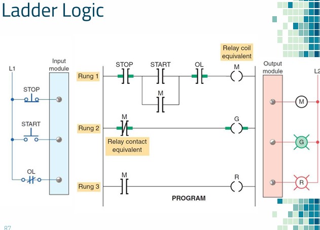
The basic logic gates are used in many circuits like a push-button lock, light-activated burglar alarm, safety thermostat, an automatic watering system, etc. Truth Table to Express Logic Gate Circuit. Gate circuit can be expressed using a common method is known as a truth table.
Learn about digital logic gates, their functions, types, and applications. See circuit diagrams and examples of basic logic gates such as AND, OR, NOT, and more.
Logic Gate (AND, OR, XOR, NOT, NAND, NOR and XNOR) Circuit Diagram
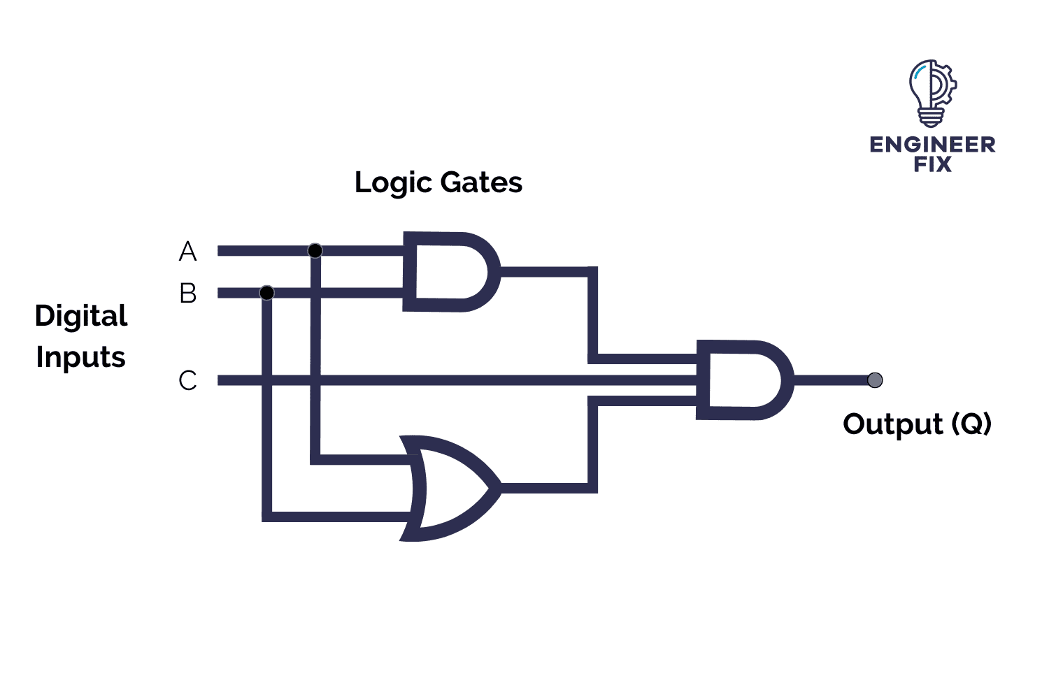
Logic gates schematic diagrams are essential tools in digital logic circuit design. They depict the logical relationships between input and output signals in a graphical form. Logic gates are the building blocks of digital circuits, and understanding their schematic diagrams is crucial for designing and analyzing complex systems. Learning Objectives In this post you will practise drawing logic gates diagrams using the following logic gates: AND Gate OR Gate XOR Gate NOT Gate First you will need to learn the shapes/symbols used to draw the four main logic gates: Symbol Logic Gate Logic Gate Diagrams Your Task Use our logic gates diagram tool If you want to use XNOR gates in a circuit, you'll find four of them in the IC 4077. Using Logic Gates in Circuits. A logic gate can be built with transistors and usually comes as an Integrated Circuit (IC). There are two classic IC series where you'll find all the logic gates; The 7400-series and the 4000-series. Both series contain chips

Dive into the world of Logic Circuits for free! From simple gates to complex sequential circuits, plot timing diagrams, automatic circuit generation, explore standard ICs, and much more. Launch Simulator Learn Logic Design. For Teachers For Contributors. Features.
