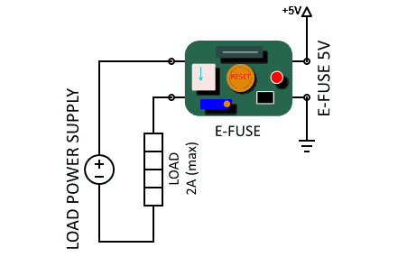
How to MAKE A FUSE Circuit Diagram The voltage drop across the sensor resistor is weighed to activate the protection circuit. The given electronic fuse circuit is based on a poly-fuse application, which is a re-settable fuse by itself. Electronic fuse circuit Fig. 1: Electronic fuse Circuit operation. Initially, when the circuit is powered, silicon-controlled rectifier SCR1 is

This symbol indicates the presence of a fuse in the circuit. Once you've identified the symbol, draw the fuse in the appropriate spot. When sketching a fuse, make sure to draw the full length of the fuse. This will ensure that it is properly placed in the circuit and that it is connected correctly. Next, connect the fuse to the rest of the How to make Electronics Fuse / Short Circuit Protection👉PCB Drawing ProgramGet a free trial of Altium Designer :👉http://www.altium.com/yt/ZAFERYILDIZ👉Subs

How to make Electronics Fuse / Short circuit protection Circuit Diagram
The electronic fuse that we use in this project is in Figure 1. Which will include important devices are transistors of 2 pcs, and Electronic devices in thyristors type of 1 piece works, together. In Figure 1, This project across between the power supply and load that will be applied immediately, When an input of electronic fuse to the power Another Simple Electronic Fuse. The electronic fuse signifies that load current is shut off as soon as an overload is detected. Actually it simply restricts the load current to a magnitude of certain amps. The next circuit will basically trigger the load current to drop to 0 %. Electronic Fuse Circuit Diagram: The complete circuit diagram for an electronic fuse circuit is shown below. As shown in the circuit, it involves only few circuits and hence it is easy to construct and implement into our designs. Here the circuit is constructed to monitor the operating current of a motor (LOAD), which operates on 12V.

Electronic Fuse Circuit Useful Steps. 1) Solder the fuse box on the Veroboard. After that, solder the After solder the I/O terminal block connectors on the Veroboard. 2) Solder a 47K resistance on the first terminal of the fuse. After that, Solder the red LEDs +ve terminal with the 47K resistor & the -ve terminal with the second terminal of the

Simple Electronic Fuse Circuit Circuit Diagram
Having a good understanding of how to create and use an electronic fuse circuit diagram is crucial for engineers today. With the right research and preparation, you can ensure that the fuse circuit you create will work effectively and protect your circuit. Whether you're a beginner or an experienced engineer, having an effective electronic Friends in this video I will show you How To Make A Simple Electronic Fuse Circuit..Simple Blown Fuse Indicator Circuit..Simple Project..Friends it is a very Schematic https://goo.gl/eIyUHaIn this video i show my homemade electronic-resettable fuse. It's made out of car 12V relay, 2leds, 6.3V zener diode, 2 ordina
