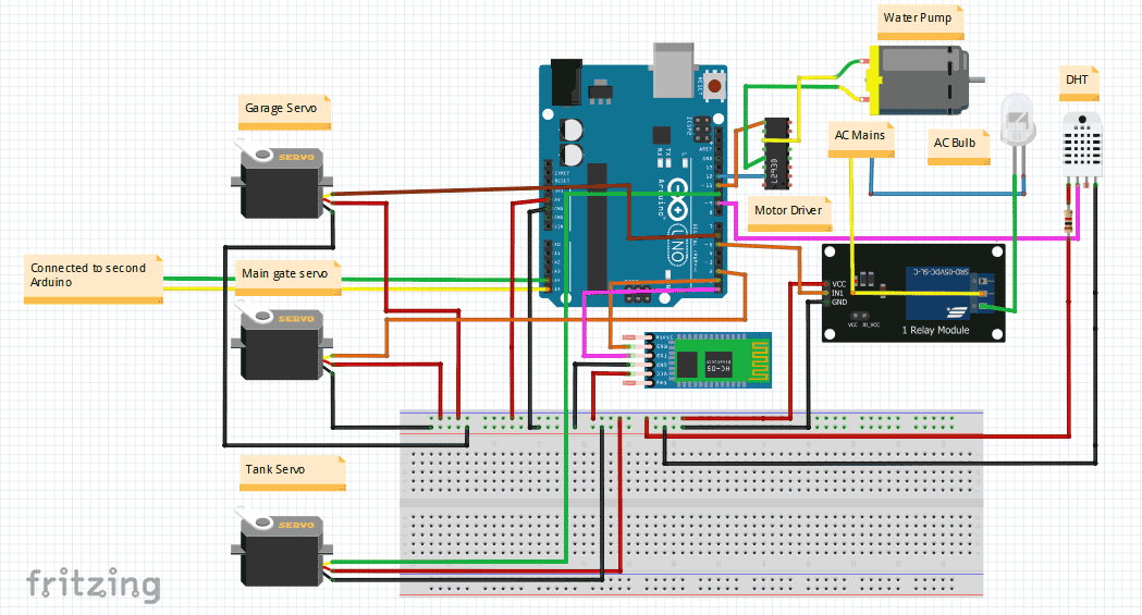
Home Automation System Using Arduino Circuit Diagram Working of Arduino based Home Automation. Make the connection for Home Automation project as given in the circuit diagram. First of all, we connect the bulb with AC powered sources and with relays as given in the circuit diagram. Then the relays are given DC power from the Arduino Uno board. Fig : circuit diagram of Home Automation using Arduino, Relay and Bluetooth Module. Interfacing with HC-05 Bluetooth Module. It is a small portable device that is used to be connected in the Arduino board so that it can communicate with mobile or smartphone.It has 6 pins, among which we are concerned with only 4 pins.

How to Connect the Bluetooth HC-05 to the Arduino. 1) Connect the Arduino's +5V and GND pins to the bus strips on the breadboard, as shown in the above circuit diagram. 2) Power the HC-05 module by connecting the 5V and GND pins to the bus strips on the breadboard. The HC-05 is powered using 5VDC but includes an on-board voltage regulator that generates a 3.3V supply to power the transceiver. In this home automation project, I have shown how we can control light, fan and other home appliances from our smartphone app and IR remote using the Arduino control relay module circuit. This Arduino controlled Smart relay circuit has two modes, Infrared mode and Bluetooth mode so we can control room lights, fan with Mobile Bluetooth and IR Arduino's powerful features are a good fit for popular segment of applications - home automation. There is a large scope of home automation applications that we can build by using the Arduino board. Below is the list of some DIY arduino home automation projects which we shared with detailed description of required components, circuit diagrams
Home Automation with an Arduino: A Basic Tutorial Circuit Diagram
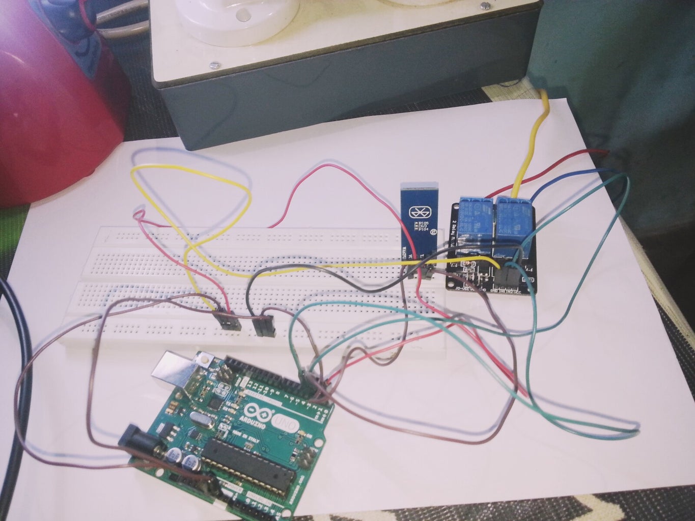
Before designing the PCB first I have made the circuit on the breadboard for testing. During testing, I have uploaded the Arduino sketch to the Atmega328P microcontroller using a USB to Serial interface board (FTDI232).. Then upload the code to the ESP01 board (Code_ESP8266_SmartRelay_V5) and connect it with the Atmega328P microcontroller.. After that tried to control the relays with WiFi, TV An advanced home automation project with Arduino Uno and Bluetooth sensor to control it, anytime from anywhere. Home Automation Using Arduino and Bluetooth Control Nov 5, 2018

Hi, in this article, we are going to see the Wiring diagram for Smart Home Automation System using Arduino. This automation system will help you to control your home appliances such as lights, fans, and others using a smartphone wirelessly.

Home Automation Using Arduino and Bluetooth Control Circuit Diagram
In this Arduino project, we will create a home automation system that will control home appliances via HC-05 Bluetooth and an Android application. HC-05 Bluetooth will be used to communicate with Arduino using an Android Application known as the S2 Terminal. There are also other apps but this is free and easy to use.