Fuse Circuit Diagrams This rather defeats the purpose of a very fast electronic fuse. Some circuits are more amenable to applying a delay than others. It's easy with the Figure 5.1.1 circuit (see Figure 5.1.2), but harder (and less predictable) with the circuits shown in Figures 5.1.3, 5.1.4 and 5.1.5. including but not limited to all text and diagrams, is the Creating an electronic fuse circuit diagram entails understanding the necessities of the circuit, including how much current you're expecting to pass through it. This will help you determine the size of the fuse you need to install — too small of a fuse and it won't provide enough protection to the circuit; too large and it might prevent Fuses, positive temperature coefficient (PTC) resistors, and active circuit protection are a few of the protection devices with varied capabilities and drawbacks. Fuses are traditionally considered as protection devices used to isolate overload or short-circuit faults from the main system. Although these devices

Electronic DC fuse circuit diagram. The current flowing through the thyristor T1 will sink below the holding level when the current is rerouted through the transistor T2 2N3055. T2 and RS are built into the electronic fuse circuit for this purpose. If the voltage drop at RS exceeds above base-emitter-diode trigger voltage of the T2, the A basic electronic fuse circuit diagram is composed of symbols representing the components of the circuit, including the switch, the fuse, the capacitors, the inductors and the resistors. The purpose of each component is also represented by its own symbol. As such, understanding the symbols used in the diagrams is essential for readers to

DC Electronic Fuse Circuit Construction & Working Circuit Diagram
Test the electronic fuse by applying power and pressing the start/reset button S1. Verify that the circuit activates and deactivates as expected when the current exceeds or falls below the threshold. Note: By following these steps and referring to the schematic diagram provided, you can build the described DC electronic fuse. The given electronic fuse circuit is based on a poly-fuse application, which is a re-settable fuse by itself. Electronic fuse circuit Fig. 1: Electronic fuse Circuit operation. Initially, when the circuit is powered, silicon-controlled rectifier SCR1 is 'off.' Relay RL1 energizes through the polyfuse and the load is connected through the In some experiments, electronic circuits require fuse protection. The circuit may be difficult. Because, often short, to change the fuse every time. , Thus wasting time. To solve this problem, we Build this electronic fuse limiter circuit, so instead of plain fuses. By it can cut off the current immediately. When a short circuit as well.
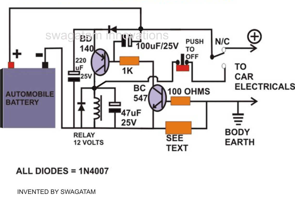
The complete circuit diagram for an electronic fuse circuit is shown below. As shown in the circuit, it involves only few circuits and hence it is easy to construct and implement into our designs. Here the circuit is constructed to monitor the operating current of a motor (LOAD), which operates on 12V. You can replace the load with any circuit

Electronic Fuse Circuit Diagram
Electronic Fuse Schematic Diagram . Current fuse can be set to the maximum output current (about 10 mA) up to the maximum allowable current of the transistor T1 (BUZ11 - 20A). the fuse is power supply of +5 V with integrated stabilizer 7805, +5 V voltage reference voltage and therefore stability is important to determine the accuracy of the