Electronics projects diy Diy electronics Circuit Diagram The arduino board of the meter circuit is powered using a power jack cable (6) that comes from the power supply circuit (8). The power supply board has been modified to obtain 12V instead of 24V. The positive pin of the CC LED from the power supply circuit is wired to the mode connector of the Meter Circuit. Then there are knobs, switches, connectors, voltage and current display so at the end of the day you are looking at $100-$200 just for a box that looks like power supply. Not a good start by any means. So I started looking through Chinese markets for a dirt cheap "promo" power supply's. And what do you know! They go as cheap as $50. To get adjustable high voltage, we will convert the adjustable dc from the LVPS into adjustable ac at a frequency of about , by means of an LC oscillator. Then, a step-up transformer will be used to get high voltage ac, which can be turned into dc with a half-wave voltage-doubler rectifier. Here is the block diagram: Figure 1: HVPS block diagram

And many other specialized niches. Unfortunately, laboratory grade high voltage power supplies are rather costly. Luckily, there is a much less expensive way to put high voltage experiments into the hobbyists reach. This article shows how to build an inexpensive and adjustable 5 kV to 30 kV high voltage supply from a commercial laser supply. Highlight features of the superb lab power supply include: Nominal Voltage: 24V. Nominal Current: 3A. Output Voltage Ripple: 0.01% (According to the specs of the power supply circuit kit). Voltage measurement resolution: 10mV. Current measurement resolution: 1mA. CV and CC modes. Over-current protection. Overvoltage protection.
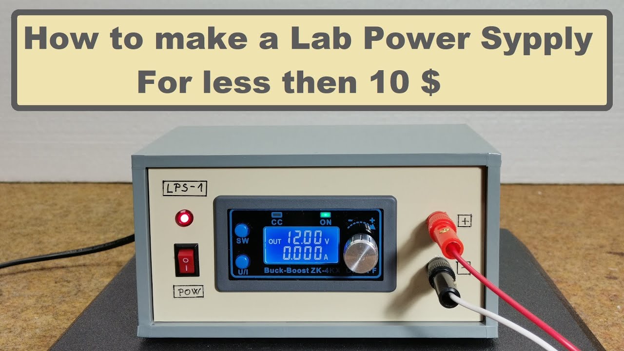
Superb Lab Power Supply : 15 Steps (with Pictures) Circuit Diagram
So, it often makes sense to use a variable power supply. In this circuit, we'll design a lab power supply to provide voltage and current requirements for testing various circuits and devices. Here are the lab's essentials: 1. Must provide a regulated output 2. Must supply the required current to the circuit under test 3. In this video I am showing how to build an adjustable high voltage power supply with an output voltage of up to 30 kV. The maximum output current of 20 mA. T

Here's a simplified overview of how to make a basic high voltage power supply, often used for applications like testing or educational purposes. Components Needed. Transformer: Step-up transformer (e.g., 120V AC to 10kV AC). Rectifier: Diodes capable of handling high voltage (e.g., silicon diodes). Once again in order to make sure the lab power supply works with perfect stability, the feedback loop's bandwidth is restrained by the resistor R19 and the capacitor C8. In case the voltage drop developed across the resistor R17 becomes higher than the value as adjusted by the preset P2, the current limiting feature of the circuit kicks in and