Electronic Circuits Diagram Controller robot circuit Circuit Diagram Insert 40-amp Circuit Breakers into the positions on the PDH corresponding with the Wago connectors the motor controllers are connected to. Note that the white graphic indicates which breakers are associated with which terminal pairs. If working on a Robot Quick Build, stop here and insert the board into the robot chassis before continuing. The line follower robot needs mechanical arrangement of the chassis. I have used a 4WD Acrylic chassis. The two IR sensors are mounted on the fron of the robot facing with the diodes facing towards Earth. When robot is placed on the fixed path, it follows the path by detecting the line. The robot direction of motion depends on the two sensors

This circuit design features an Arduino UNO and a variety of motors and sensors to create an autonomous robot capable of navigating its environment while avoiding obstacles. Utilizing an ultrasonic sensor for distance measurement and a servo motor for directional control, the robot can make real-time decisions to move forward, backward, or turn In the first part I show how to design the arm, the second part shows how to design the base, and the third shows how to design the mount. After all of the Computer Aided Drafting (CAD) and 3D modeling in my past articles on making a robot arm (see links above), we are now ready to explore and expand on ways to control the robot arm. We previously built few IoT based robots, which can be controlled from the webserver. In today's article, we are going to build a gesture-controlled robot using Arduino, MPU6050 Accelerometer, nRF24L01 Transceiver pair, and L293D motor driver module. We will design this robot into two parts. One is the Transmitter, and the other is the Receiver.
How to Build a Robot Circuit Diagram
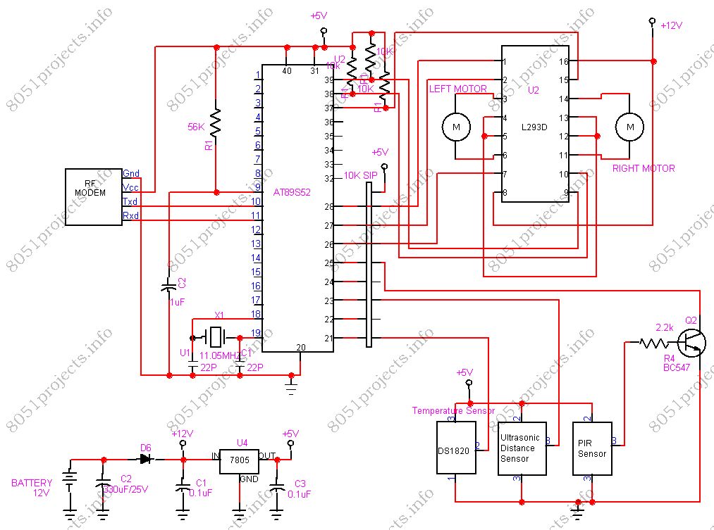
Robot Journals Robot Theory Conferences - THE $50 ROBOT - STEP-BY-STEP ROBOT TUTORIAL STEP 3b: CONSTRUCT THE CONTROLLER. Electronics, Continued Continuing from Step 3A, I will now show you the schematic we will use to build the circuit, followed by step-by-step instructions on how to wire your robot controller together. Depending on the values received from the IR module, the Arduino controls the two motors separately. Thus, making the robot turn left or right to avoid the obstacle. L293 MOTOR DRIVER: The driver has 2 inputs for power, 4 points for motor control inputs, and 4 points for motor control outputs. That is a set of 2 inputs and 2 outputs for each motor.
Make Your First Arduino Robot - the Best Tutorial!: Smartphone controlled , obstacle avoiding and wall follower robot. "If you are not using the shield but using the l293d IC or module then visit my blog post's last section for the circuit and program." Hc-sro4 ultra sonic sensor - Buy here; Hc-05 bluetooth module - Buy here; 2 x Gear motor The robot will still operate, because all of the components chosen for the Teensy can operate on a lower voltage. However, the onboard regulator on the Teensy will ;be running unregulated. Optional Items. I want a way to control the board through my smart phone at some point, so I included a BLE device in the schematic.

Gesture Controlled Robot Using Arduino : 7 Steps Circuit Diagram
Explore 75+ DIY robotics projects with detailed circuit diagrams, source code, and complete instructions.Whether you're a beginner or an advanced maker, you'll find exciting projects using Arduino, Raspberry Pi, ESP32, and other microcontrollers.From line-following robots to AI-powered bots, our tutorials make robotics easy to learn and build.
