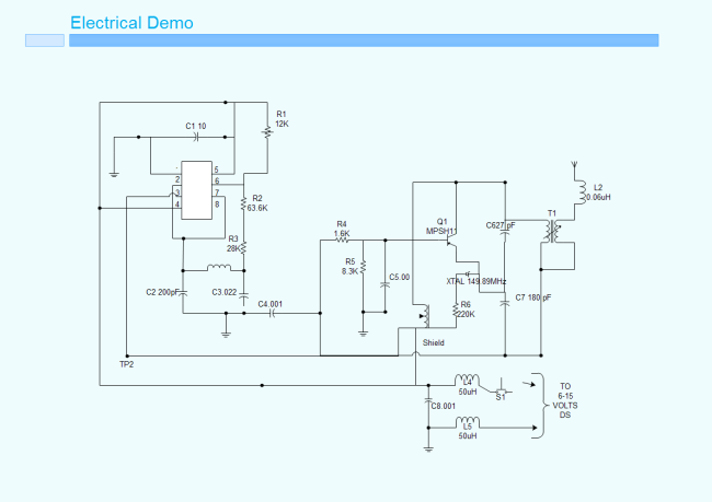
Electronic Circuits And Diagrams Circuit Diagram Introduction to Basic Electronic Circuits This article is an introduction to very simple electronic circuits. I've kept this introductory article as simple as possible for readers that are new to electronics. An electrical schematic is a diagram that shows how all of the wires and components in an electronic circuit are connected. They're like a map for building or troubleshooting circuits, and can tell you almost everything you need to know to understand how a circuit works.

Learn how to read and understand a simple electronic circuit diagram with our step-by-step guide. Explore basic components and their connections. Learn the basics of circuit diagrams or schematics for electronics with this tutorial. See examples of simple circuits, component symbols, connections, and rules for drawing diagrams.

Basic Electronic Circuits Explained Circuit Diagram
Explore Simple Electronics Circuits and Mini Projects Ideas. These free electronic circuits are properly tested and can be found with schematic diagrams, breadboard image or PCB, a detailed explanation of working principle and a demonstration video. The various small basic electronic circuits explained here can be effectively applied as building blocks or modules for creating multistage circuits, by integrating the designs with each other. We will begin the tutorials with resistors, and try to understand regarding their working and applications. But before we begin let's quickly summarize the various electronic symbols that will be used

What is a simple electronic circuit? See many examples of electronic circuits for beginners and hobbyists to build quickly and inexpensively.

Electrical and Circuit Theory Circuit Diagram
Learn how to build simple electronic circuits for beginners with this step-by-step guide. Includes components, diagrams, troubleshooting & safety tips! Learn electrical and circuit theory with our tutorials on Ohm's Law, Kirchhoff's Laws, resistance, capacitance, inductance, and much more! Basic Electronic Circuits used in Projects The list of basic electronic circuits used in projects is discussed below with appropriate circuit diagrams. Astable Multivibrator using 555 Timer: The 555 timer generates the continuous pulses in astable mode with a specific frequency that depends on the value of the two resistors and capacitors.
