Electrical Engineering Stack Exchange Circuit Diagram Tips for Wiring and Troubleshooting a Relay Module. When wiring a relay module, it is important to follow these tips to ensure proper installation and troubleshooting: Double-check the connections: Before powering up the circuit, double-check all the wiring connections to make sure they are correct and secure. Loose or incorrect connections can Get a relay module: 5V 2-channel relay module; 5V 1-channel relay module; 5V 8-channel relay module; 3.3V 1-channel relay module; Relay Pinout. The following figure shows the relay module pinout. The six pins on the left side of the relay module connect high voltage, and the pins on the right side connect the component that requires low voltage It's important to choose a relay module that is compatible with your Arduino board and can handle the voltage and current required for your specific project. The first step in wiring an Arduino relay module is to connect the module to the Arduino board. The module typically has four pins: VCC, GND, IN1, and JD-VCC.

2) Connect the other end of the jumper to the S PIN on the relay module. The connection will look like the image below; 3) Make a connection between Arduino 5 V pin and the (+) PIN on the relay module; 4) Make a connection between the Arduino GND pin and the (-) PIN on the relay module; Step 2: Wiring the Relay board to the Supply and the load Step 1: Wiring. Connect the Relay Module to the Arduino board as follows: Connect the module's VCC pin to the 5V pin on the Arduino. Connect the module's GND pin to the GND pin on the Arduino. Connect the module's signal pin to a digital pin on the Arduino (e.g., D2).
Mastering the 8 Relay Module Wiring Diagram: A Step Circuit Diagram
Example: Arduino-Controlled Relay Module. To control a relay module with an Arduino, follow these steps: Connect the relay module's control input to an Arduino digital output pin. Connect the relay module's ground to the Arduino's ground. Write Arduino code to control the relay by setting the digital output pin high or low.

In conclusion, wiring an 8 relay module involves connecting the VCC and GND pins to the power supply, and the IN pins to the digital output pins of your microcontroller or Arduino. Once properly wired, you can control multiple electrical devices using the relays on the module. Step-by-step guide to wiring the 8 relay module This guide covers the basics of. In this tutorial, we'll learn how to use a Relay Module with Arduino to control high-voltage devices safely and effectively. This guide covers the basics of. The wiring and code are similar to a single-channel relay, but you need to specify the appropriate control pin for each relay. Learn how to use relay with Arduino, how relay works, how to connect relay to Arduino, how to code for relay, how to program Arduino step by step. The detail instruction, code, wiring diagram, video tutorial, line-by-line code explanation are provided to help you quickly get started with Arduino. Find this and other Arduino tutorials on ArduinoGetStarted.com.

How To Use A Relay With Arduino Circuit Diagram
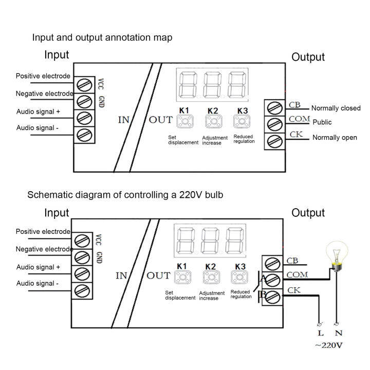
2. Wiring the Power Supply to the Relay Module. When wiring the power supply to the relay module, it is essential to follow the manufacturer's instructions. Typically, the relay module will have a set of input terminals marked with labels such as "VCC" (power supply voltage), "GND" (ground), and "IN" (control signal).
