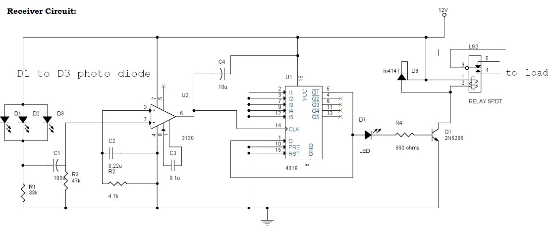
Electrical Engineering Portal Bangladesh Circuit Diagram Construction of Remote Control ON-OFF Switch. To construct the remote control ON-OFF switch circuit, connect the CD4017 IC to power and ground, and connect the IR sensor output to the clock input of the IC. The outputs of the CD4017 IC should be connected to the base terminals of the BC547 transistors through appropriate resistors. When the user presses a key again, the second pulse arriving at the CLK line increments the counter by 1. Since Q2 is wired to the Reset input , the second key press actually brings the CD4017 IC back to the power-on-reset conditions with Q0 High. Thus, it simply operates as an ON/OFF toggle switch controlled with any key of an infrared remote. How to make simple wireless remote control switch without relay, IR receiver remote control. ( CD4017 Remote control circuit, remote control light )Note: Thi
( IR sensor project )This is an IR receiver using a TSOP 1738. This is a v Simple wireless Remote control switch using TSOP 1738, IR Receiver Remote control.
IR Remote Control Switch : 7 Steps Circuit Diagram
We can also control it using a phone that have IR sensor.(For example in MI phones which support MI Remote APP) Step 11: PCB-way for a Better Circuit Here i used mostly components without a proper circuit board .You can build it in much better and efficient way using a PCB. How to make Wireless Control at Your Fingertips: DIY IR Remote SwitchRequired Components:-1) BC547 Transistor 2) 150 ohm Resistor 3) Red LED4) 1N4007 Diode5)

An IR remote control (RC) switch is a simple electronic configuration used to attain dynamic control of AC/DC with the push of a button. IR remote control switches use IR rays to communicate with one another and allow the user to gain access to any place or object locked behind the said switch. With the current onset of the COVID-19 pandemic. This project describes a technique of adding the remote control feature to an electrical appliance. The goal is to construct a black box where you can plug-in your 120V AC appliance (it can be easily modified for 220 V mains supply too) and control the ON and OFF operations with a TV or DVD remote that uses modulated infra-red (IR) pulse train of 38 KHz frequency.

How to Make Remote Control ON Circuit Diagram
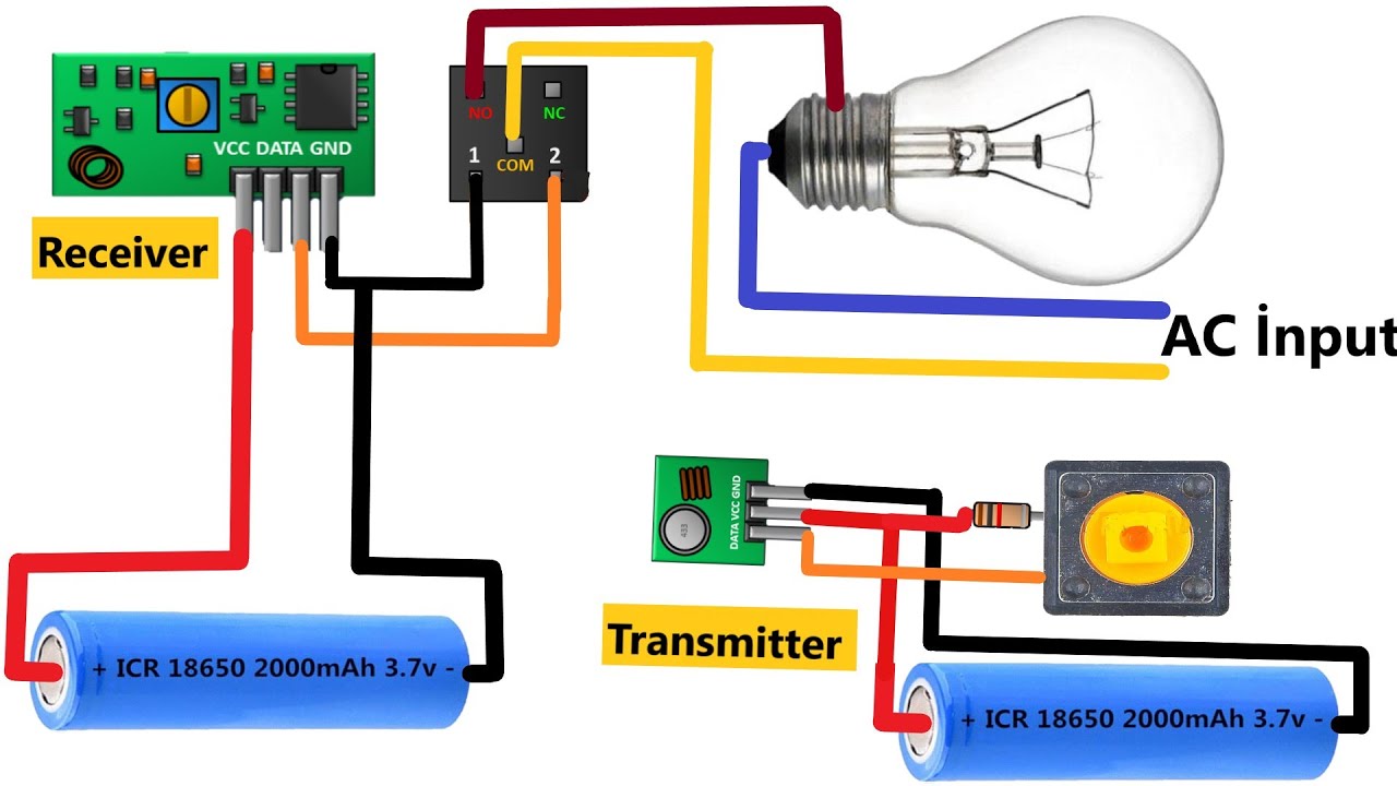
Point your IR remote control at the TSOP312 receiver module. Press any button on the remote control. You should see the relay click and its onboard LED will turn ON. Press the button again. The relay should click again, and the LED will turn OFF. Note that this circuit can be a bit sensitive to noise from other IR sources. Infrared Remote Control Circuit using IC 555 and Transistors. Here's a straightforward infrared switch designed for remote control purposes. It utilizes a typical IR LED and IR diode detector pair, specifically the CGIY89A/BPW50 components. Transmitter Circuit. The 555 IC based IR transmitter circuit generates a series of pulses to drive the IR
