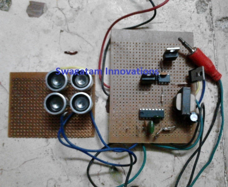
DIY Components Circuit Diagram A sound sensor switch is a type of switching device that responds to an audio input. With a proper sound-activated switch, dynamic control by sound may be very useful, not just on robotic systems but also for home automation, for example, a sound-activated light responding to a knock on the door or a hand clap.So, in this project, we will build a simple sound sensor switch using the LM393N
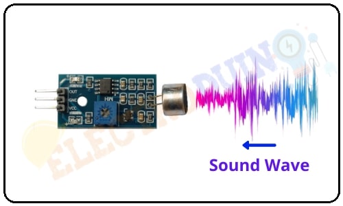
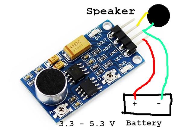
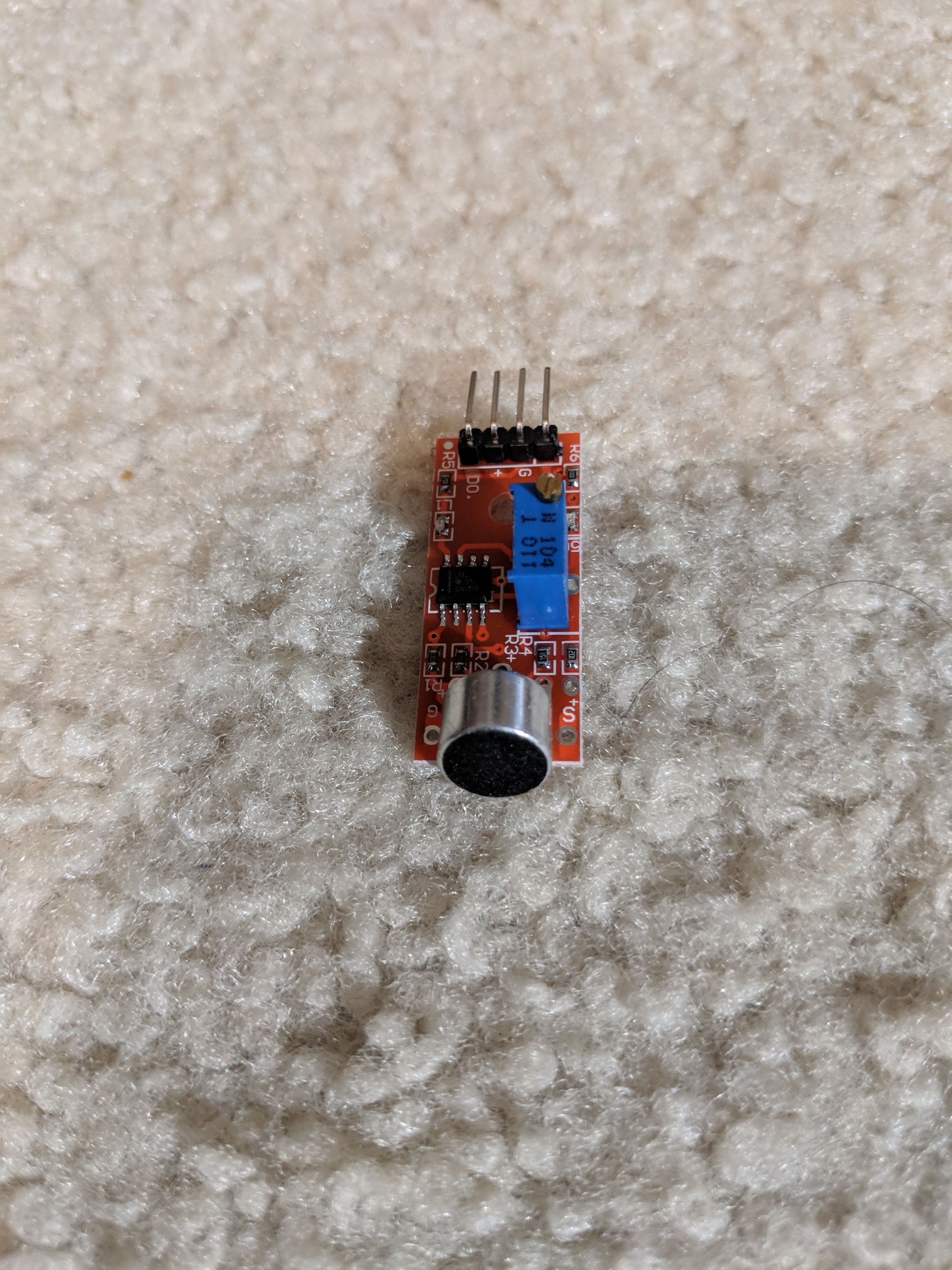
Sound Sensor Pinout. The Sound sensor module has 4 pins VCC, GND, Digital Out, and Analog Out. We can either use the AO pin as an output for analog reading or the DO pin as an output for digital readout. The Sound sensor pinout is as follows: VCC is the power supply pin of the Sound Sensor that can be connected to 3.3V or 5V of the supply. But
Arduino Sound Sensor: Control an LED with Sound Circuit Diagram
Hey friends.. In this video I made a Sound sensor at home. The factory made sensors are very costly, so I decided to make it at home.Sound Sensor | How to ma Same as the first graph, a sound sensor have four pins. VCC and GND will connect to 5V and GND on Arduino. D0 need to wire with any digital pin which is 7 in my circuit on Arduino board. That is how a sound sensor should wire. Later, the Led need to be wired either. The short side should connect to ground on Mini breadboard.
Common Issues and Solutions. If your Arduino Sound Sensor isn't working, try this: LED not responding: Ensure the LED is correctly placed according to its polarity and that all connections are secure.; No reaction to sound: Adjust the sensitivity of the sound sensor, if possible, or check the connections to pin 2.; Conclusion. You now have a sound-activated LED switch!

Arduino Tutorial - Arduino Getting Started Circuit Diagram
Make sound sensor at your home. DIY Homemade Sound Sensor. Make sound sensor at your home. Jun 18, 2021 Circuit Diagram of sound sensor. Comments. Only logged in users can leave comments. login. Anonymous user. Table of contents. Intro. 1. 0. Report content
The sound sensor is capable of detecting the presence of sound in the surrounding environment. It can be used to create sound-reactive projects, such as clap-activated lights or a sound-activated pet feeder. In this tutorial, we are going to learn how to use Arduino and sound sensor to detect the sound. In detail, we will learn: This easy to build circuit will let you detect sound with your ARDUINO, You can buy a pre made sound detection sensor module but they don't work worth a sh!t from my experience. The picture above shows you the simple circuit design, just build that and it will work better than most of the pre maid modules you can buy. PARTS LIST: 2 - 10kΩ A typical sound sensor module consists of the following pins: VCC - Power supply (3.3V to 5V); GND - Ground; A0 - Analog output (provides variable voltage based on sound intensity); D0 - Digital output (HIGH or LOW depending on a preset threshold). Specifications. Below is a table with the specifications of a typical sound sensor:
Sound Sensor with Arduino Tutorial Circuit Diagram
Attach the AND gate, switch, and sound sensor to the breadboard. If you had bought the sound sensor that looked like the one I previously linked, then all you need to do is plug it into the breadboard. The sound sensor itself will have 4 pins that are individually labeled. AND gate pin instructions: Pin 14 ----- Power. Pin 7 ----- Ground