DIY Arduino Robotic Arm Project with Circuit Diagram Code In this tutorial, we are going to design an Arduino Uno based Robotic Arm from some cardboards and servo motors.Entire process of construction has been explained in detail below. Here in this project Arduino Uno is programmed to control servo motors which are serving as joints of Robotic arm.This setup also looks as a Robotic Crane or we can convert it into a Crane by doing some easy tweaks. Some 6DOV DIY robot arm kits come with all relevant parts (aluminum bits, servo disc and servo motors) included, while others don't. In my case, I ordered the kit and then realized it did not include the motors and the disks. So I had to order them separately. However, the advantage of ordering the parts separately is the flexibility of choosing the motors that will be used in the project.
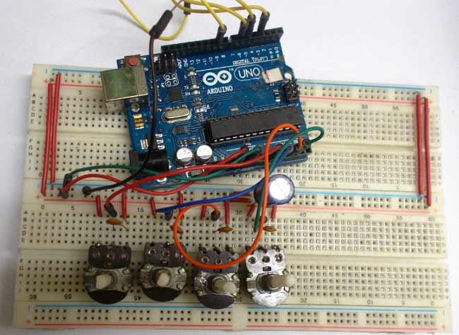
Learn how to create a simple robotic arm with servo motors that can be controlled with external potentiometers. Servo control is achieved with the use of the servo library which removes the need for coding the PWM duty cycle. One of the advantages of using the servo library is that any digital I/O pin can be used for timing and control with After uploading the code to the board successfully, Open 'Serial Monitor' you can find it in the Tools option. When the Serial monitor starts the Arduino will reset. Now you can control the robotic arm using the master arm. But nothing is being recorded. To start recording, Enter 'R' on the monitor now you can perform the moves you wish to record. First, we will see the circuit diagram for the project. The following image shows the necessary circuit for the robotic arm. The circuit is actually very simple and involves only Arduino and 4 servos. But the construction is more complex compared to the actual circuit itself. NOTE: The power supply to the servos should not be given from Arduino.
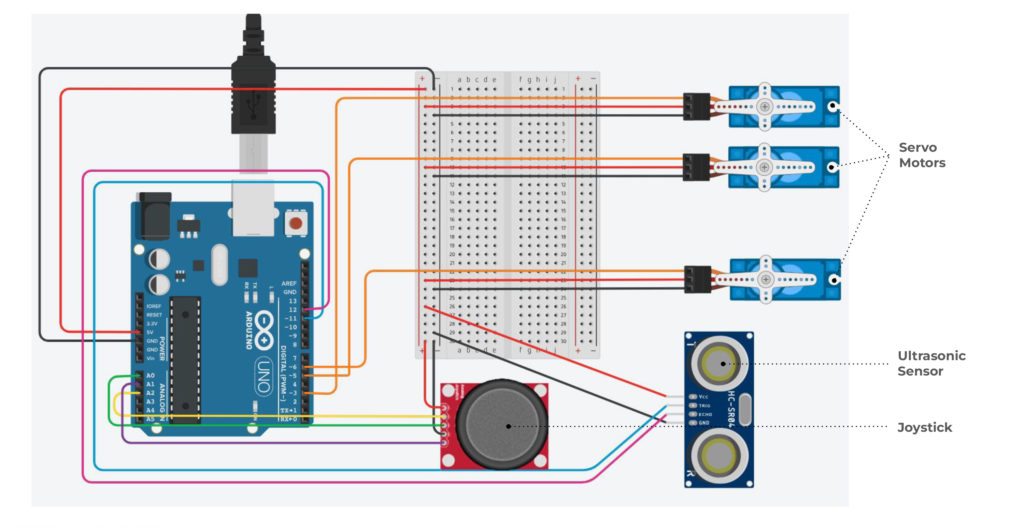
Joystick controlled Robotic Arm with Arduino: Wiring Diagram, Code ... Circuit Diagram
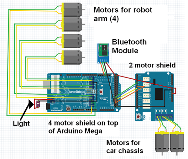
Code Overview. This code controls a 3-DOF robotic arm using three servo motors (base, shoulder, and elbow) via an Arduino.The arm's movements are controlled using a potentiometer for base control and joystick axes for the shoulder and elbow. Additionally, the angles of the servos are sent via serial communication to update the 3D simulation of the robotic arm in a web interface (using Three.js). Make sure you have set the correct baud rate in the program that matches with your Bluetooth module baud rate. To be honest, this code and the Android app don't work very well. I made an updated version of the robot arm in my Arduino Robot Arm and Mecanum Wheels Platform project, where I use different approach to control the arm.
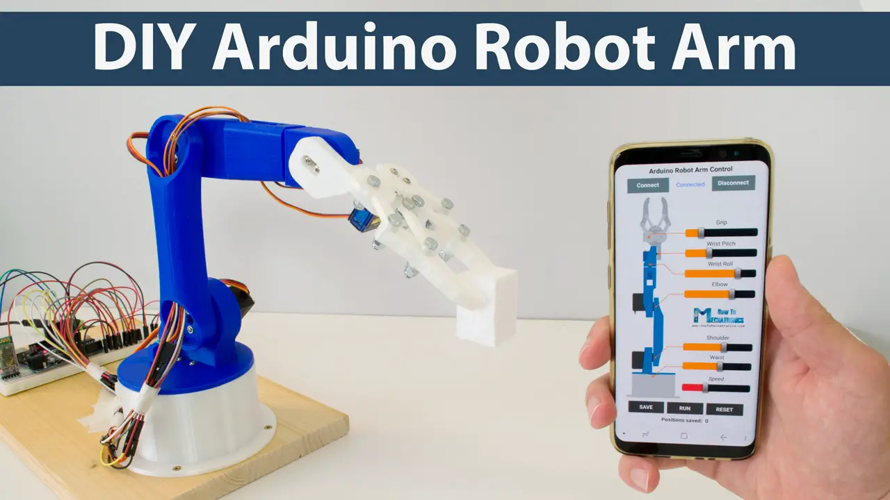
In the app, you are able to: connect your phone to the arm, load a saved program to the Arduino, start or stop the arm from running the program and create a new program. How to control your arm? First, choose your robot arm in the device list ; Then, click the "manuel" button at the top to switch to the automatic control Arduino Robotic Arm Project - Working. The mini-robot arm uses four servomotors to move the arm. Servomotors are controlled by Arduino and connected to the PWM pin of Arduino. There are eight buttons in the android app. Out of these, four buttons are used to control the four servo motors. One button is used for clockwise rotation and other is Arduino Robotic Arm: In this instructurable I will show you how to make a simple robotic arm controlled by 4 servos , 2 analog joysticks, and an Arduino UNO. It is very similar to my "2 Servos + Thumbstick" instructurable. This tutorial is in particular to help out…