Design and Implementation of a Wireless Circuit Diagram 2.1 Existing System The system does not include water level monitoring, which is expensive and difficult to maintain. The accuracy of the water meter is low. The user experience is clear for everyone. It provides greater accuracy and saves time. This system does not have a water pressure monitoring function. 2.2 Proposed System
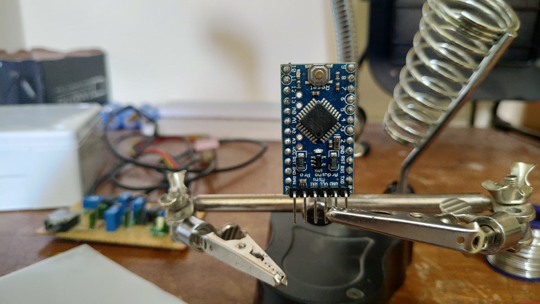
In this IoT project, we will create a water level monitoring web server using an HC-SR04 Ultrasonic sensor and ESP32. It will be a contactless water level measurement system. First, we will learn to interface HC-SR04 with ESP32. After that, we will see program our ESP32 board with the ultrasonic sensor to build our water monitor web server. 2.3. Capacitance Based Water Level Indicator 17 2.4. Conductivity Based Water Level Indicator 19 2.5. Ultrasonic Type Water Level Indicator 22 2.6. Comparison of some common types of water level indicators 25 2.7. Specialty of Transistor 26 2.8. Project Description 28 2.9.

IoT Based Water Level Control & Monitoring with ESP8266 Circuit Diagram
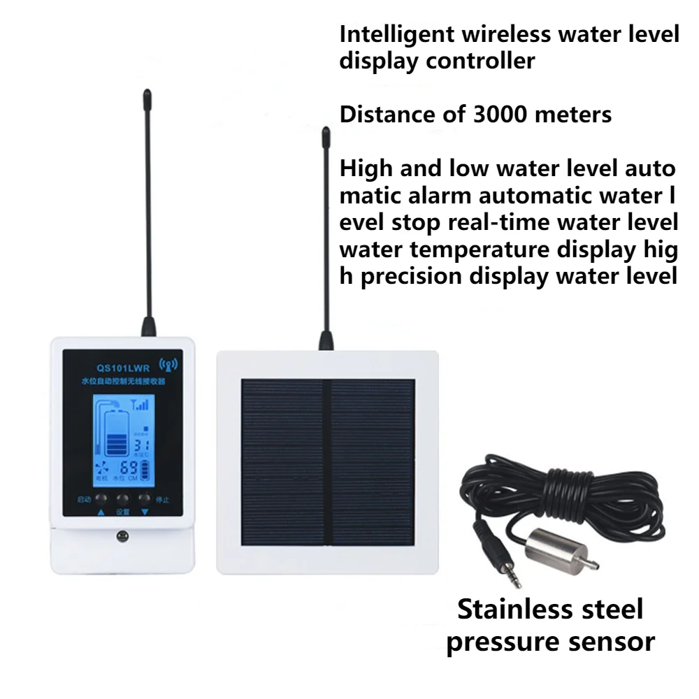
simple wireless based water level monitoring and control system is presented in this paper. 2. PROPOSED MODEL In this paper, we present a wireless based Water Level monitoring and control system using Arduino UNO and Bluetooth Modules is shown in figure 2, which help the user to be aware of the water level in the tank through an In this project, we will build Water Level Monitoring System Project using Arduino & GSM Network. In one of our previous projects, we build Inductive Water Level Indicator using some ICs and transistor and we also build IoT Water Level Indicator. But this is a different project that uses Arduino as a processing unit.
ing system is needed for monitoring the level of water. There are much of the technologies used today to execute the basic tasks as waterlevel measurement, waterquality characterization and so on. For monitoring the level of water, the system is a kind of structure which measures water deepness through ultrasonic sensor technology1.
PDF Use of Wireless Sensor and Microcontroller to Develop Water Circuit Diagram
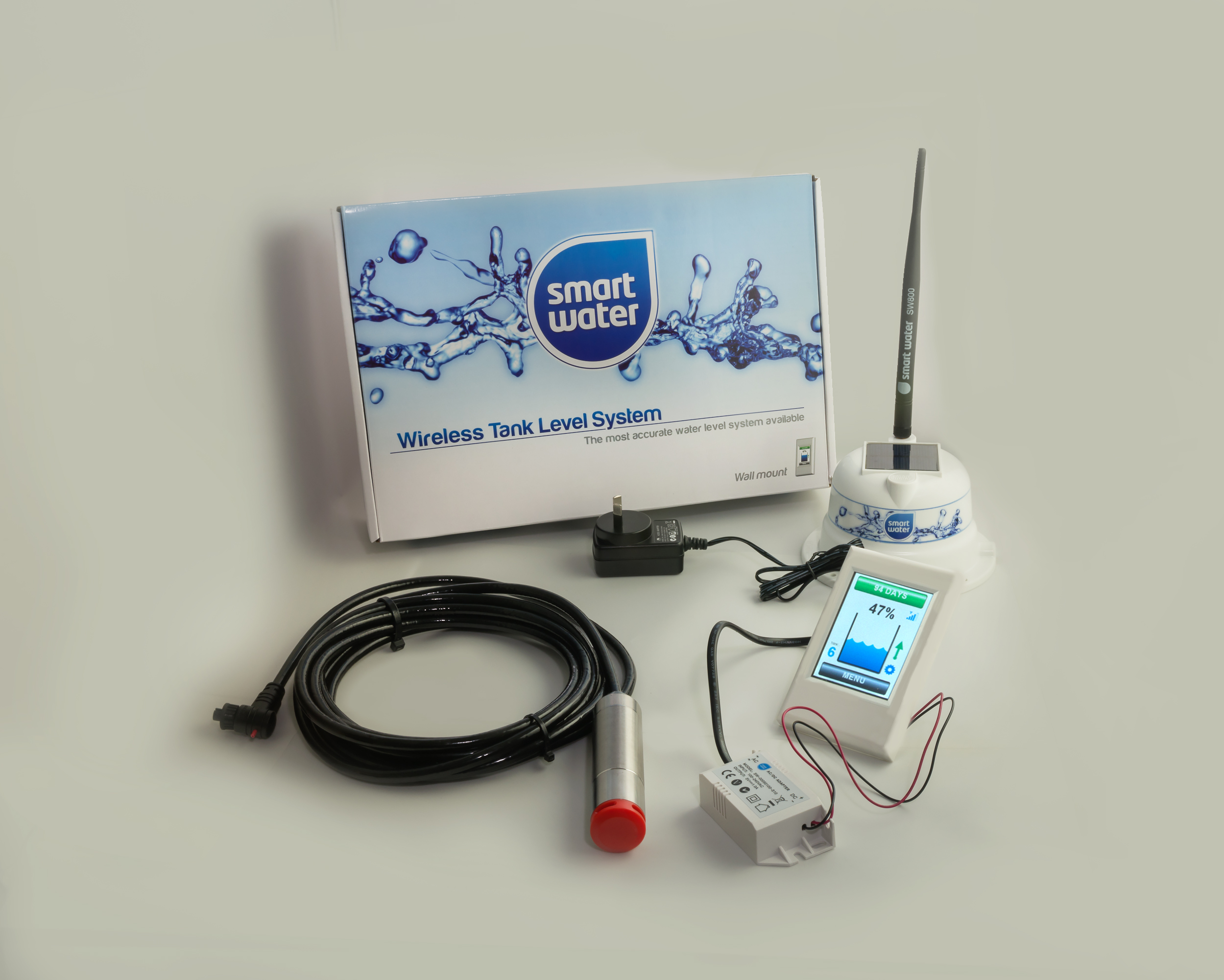
In this Instructable, we'll guide you through building your very own WiFi Water Level Sensor S1, a smart device inspired by advanced water monitoring systems.This project is perfect for DIY enthusiasts who want to create a custom, low-cost and high quality solution for monitoring water levels in tanks, reservoirs, wells, or any water storage system. During the tutorial video on wireless water level controller, I covered the following topics: Quick demo on IoT-based water level monitoring system. How to make the water level detector on Zero PCB. Set up the Blynk IoT Cloud for ESP8266. Steps to add a device in Blynk IoT Cloud. Source code for the IoT-based water level sensor. Overview. In this project, we will build an IoT Based Water Level Control & Monitoring System with ESP8266 and Waterproof Ultrasonic Sensor.We can monitor the water level on Blynk Dashboard.. An Internet of Things (IoT) water level control and monitoring system is a smart, automated solution to manage and maintain water levels in various applications such as tanks, reservoirs, and swimming pools.
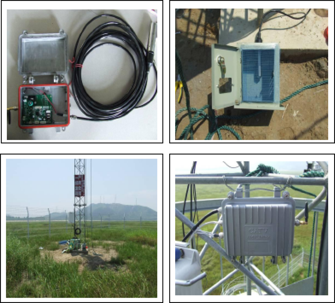
The remote wireless water-level monitoring system adopts the self-developed embedded ZKOS operating system in order to ensure an expansible and real-time system and also reduce the cost. The system timer is revised or adjusted according to the satellites synchronized through GPS chips, which will guarantee the synchronicity among the systems