DC To DC Converter Types Important Concepts Electrical Hub Circuit Diagram DC to DC Converter Circuit 1. This simple circuit lets you run a 1W LED from the battery of your car. IC MC34063 is used here as a buck converter. It is a monolithic switching regulator sub-system intended for use as a DC-DC converter. The device consists of an internal temperature compensated reference, a comparator, a controlled duty-cycle High Current DC to DC Boost Converter Circuit. The following circuit is designed to convert this 5-12 V input to a variable 15-30 V output. The converter is based on a Texas Instruments L497A, which is perfect for building a fly-back circuit. A fly-back converter's switching duration is divided into two phases. A DC-to-DC converter is an electronic circuit or electromechanical device that converts a source of direct current (DC) from one voltage level to another. It is a type of electric power converter. Power levels range from very low (small batteries) to very high (high-voltage power transmission).

Types of DC-to-DC Converters 1: Magnetic Converters. In these DC-to-DC Converters, energy is periodically stored and released from a magnetic field in an inductor or a transformer. The frequency ranges from 300 kHz to 10MHz.By maintaining the duty cycle of the charging voltage the amount of power that needs to be transferred continuously to a load can be more easily controlled. Some sample DC-DC converter circuit finished products are shown in Figure 2. A DC-DC converter can efficiently produce regulated voltage from a source that may or may not be controlled to a constant or variable load, thus ensuring proper system regulation in addition to the desired voltage level change. Figure 2. Sample DC-DC converters. A DC to DC converter is a power electronics circuit that efficiently converts a direct current from one voltage to another voltage. Without a doubt, DC-DC converters play an integral role in modern electronics. This is because they offer several advantages over linear voltage regulators. Linear voltage regulators, in particular, dissipate a lot

DC Converters Work Circuit Diagram
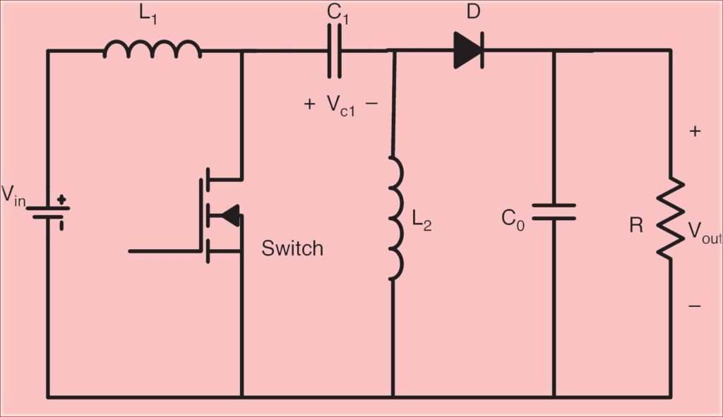
Converter circuit topologies A large number of dc-dc converter circuits are known that can increase or decrease the magnitude of the dc voltage and/or invert its polarity [1-5]. Figure 4 illustrates several commonly used dc-dc converter circuits, along with their respective conversion ratios. In each example, the switch is realized using a power

A device's DC-DC converter is allowed to have functional insulation if: - The AC-to-DC power supply uses reinforced or double insulation between the AC input and DC output. - The AC-to-DC power supply uses basic or supplementary insulation, while the secondary circuit of the DC-DC converter connects to protective Earth.
