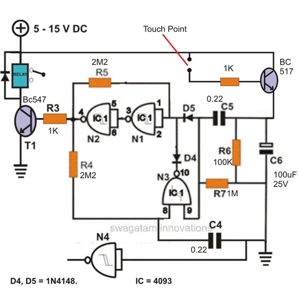
constuction of a simple touch sensitive switch circuit explained under Circuit Diagram Light Sensor Circuit Working Operation. The light sensor circuit is an electronic circuit designed using (light sensor) LDR, Darlington pair, relay, diode, and resistors which are connected as shown in the light sensor circuit diagram. A 230v AC supply is provided to the load (in this case, the load is represented with a lamp).
In this circuit, protective measures must be taken because it is isolated from the network. Light Switch Circuit Diagram. Power supply circuit is taken from the bridge rectifier D1…D4 is filtered and stabilized by R1, C1, and D5. The bridge circuit is difficult to identify in the given diagram, but it is made of R2 ….. R4, P1 and It automatically switches ON lights when the light goes below the visible region of our eyes. ( e.g in evening after Sunset ). it automatically switches OFF lights when light fall on it ( e.g in morning ) , by using a sensor called LDR (Light Dependent Resistor) which senses the light just like our eyes. The basic components of a light sensitive switch circuit diagram include a visible light sensor, a counter, a comparator, and a trigger logic circuit. Together, these components measure the level of light by comparing the current light intensity to an input level, and then trigger a light switch when the light level drops below the set threshold.
Light Sensitive Switch (schematics available Circuit Diagram
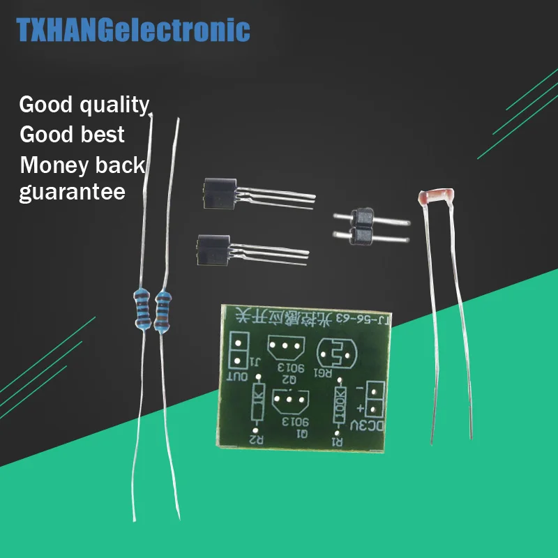
The 2SC2481 is an NPN transistor often used in low-power switching applications and amplifier circuits. In this DIY project, we will use the 2SC2481 to build a simple light-sensitive switch. This…
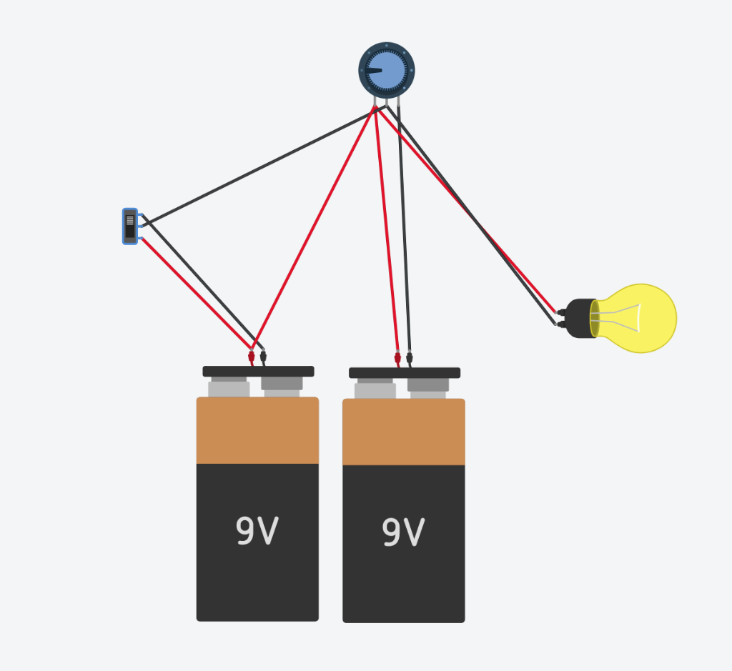
The light-sensitive switch is an ingenious electronic device that responds to the intensity of light falling on it, enabling the automatic switching of lights. In this article, we will explore a simple, cost-effective, and user-friendly light-sensitive switch circuit utilizing the popular op-amp 741. The 330K Ohm Resistor and LED can be replaced with virtually anything to trigger a signal or an event. For example, a 9 Volts Relay would be used to make an absence-of-light activated switch. To make this circuit operate in reverse (the LED turns on when there is light), simply just exchange the positions of the Variable Resistor and the LDR.
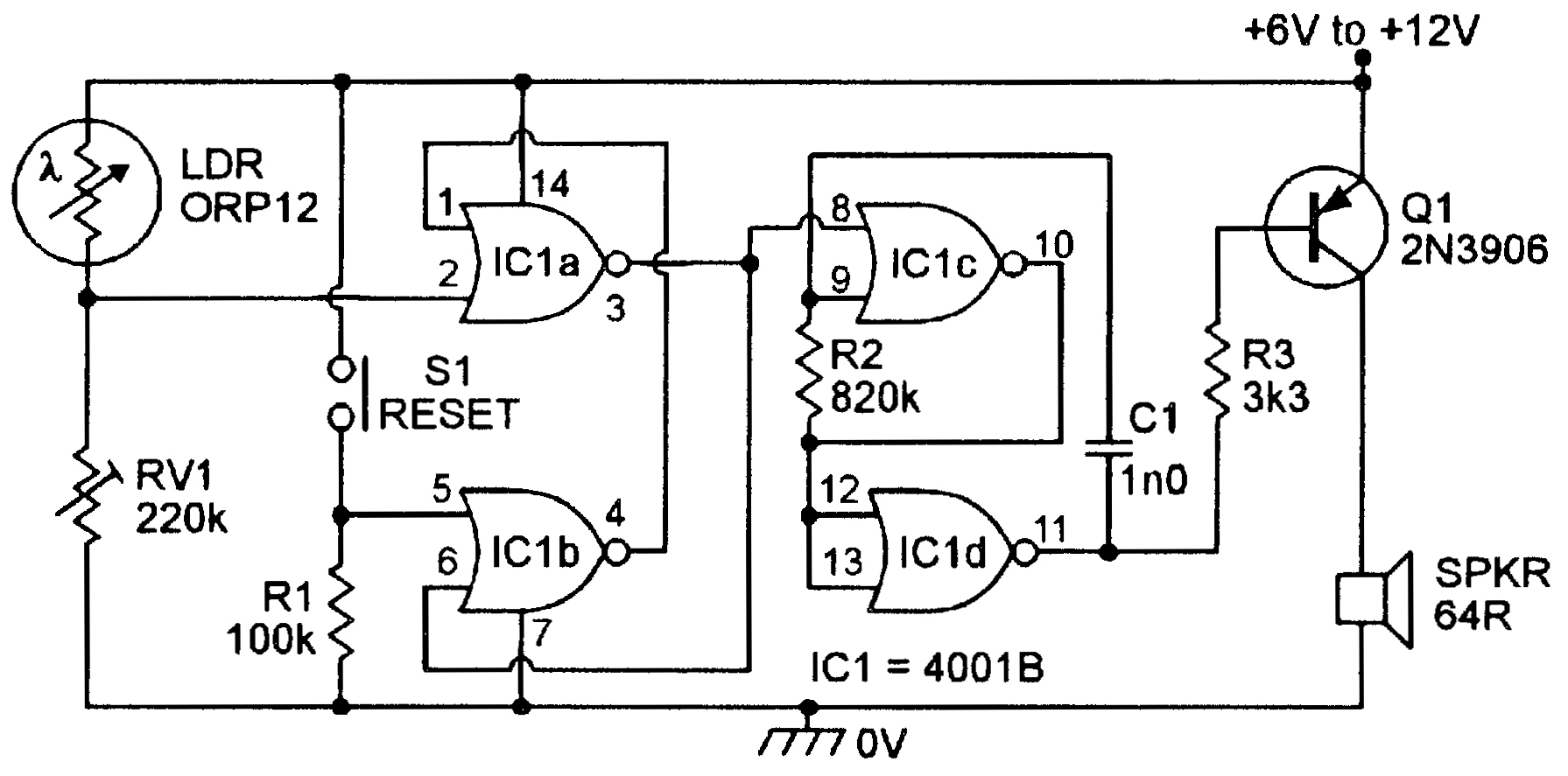
Light Sensor Switch Circuit: A Guideline in Building your Sensor ... Circuit Diagram
Using this circuit, an electrical device or an appliance like a light bulb or a fan for example, can be controlled based on the intensity of the light near the circuit. Principle behind the Circuit The main principle of this circuit is based on the working of the LDR Sensor i.e. the Light Dependent Resistor and to switch ON or OFF the light
