Connecting Arduino WiFi to the Cloud Using ESP8266 7 Steps Circuit Diagram In this tutorial, we will learn how to make a home security system using the Nodemcu ESP8266 board and the Blynk application. Also, the PIR sensor is mainly used for this project. We have done this project using the Telegram app in a previous article. You can study it from this link. Also, this project can be used for our home, place of You can also control the home appliances from the Arduino IoT Cloud web dashboard and Arduino IoT Cloud Remote mobile app if the NodeMCU is connected with WiFi.. In this project, I have used the FREE plan of Arduino IoT Cloud. In the FREE plan, you can control maximum 5 relays. When you control the relays from Arduino IoT Cloud Remote mobile app the current state of the relay also updated in
It is done by generating a Device ID and Secret Key, which together with your Wi-Fi® credentials is enough to connect to the Arduino Cloud. This guide will show you how to set up a generic ESP32/ESP8266 board to communicate with the Arduino Cloud. The official guide for connecting to Arduino Cloud using the C++ environment is found here. This Hello, welcome back to another article from SriTu Hobby. Today we are going to talk about how to make an IoT-based home security system using the Nodemcu ESP8266 module and Telegram app. Also, the PIR motion sensor and the Nodemcu ESP8266 board are mainly used for this tutorial. We have presented this project using Arduino in a previous tutorial. In the Arduino IoT Cloud tutorial, I have explained how to set up a FREE Arduino IoT Cloud account to connect ESP8266 or ESP32 and control the appliances with Amazon Alexa and Arduino IoT Cloud web dashboard and mobile app. Related Article: Arduino IoT Cloud ESP8266 Project. Arduino IoT Cloud ESP32 Project
IoT based Home Security System Using PIR Sensor, NodeMCU ESP8266, and ... Circuit Diagram
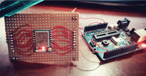
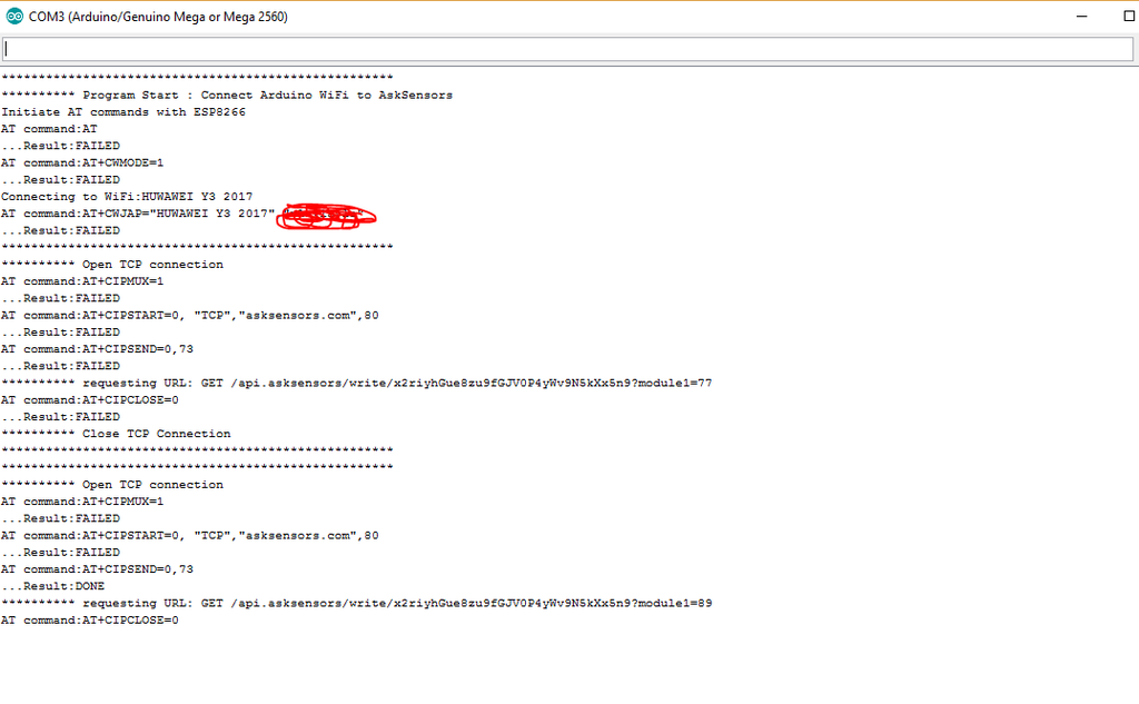
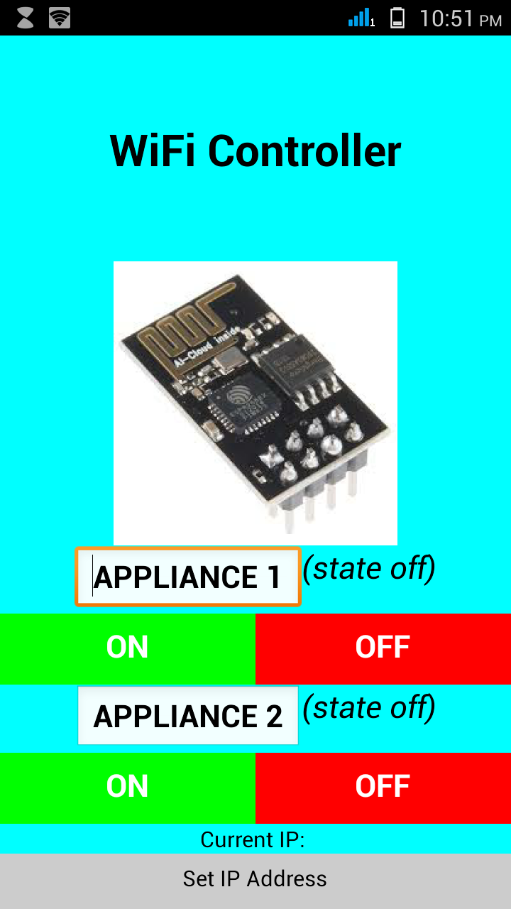
Security of one's home is one of the biggest concerns for the majority of people out there. Not everyone can afford the expansive and sophisticated home security available out there in the market. So in this tutorial, we are going to learn how to build an IoT based Home Security system using the NodeMCU ESP8266 module and Adafruit IO. The Arduino code communicates with the ESP8266 WiFi module using AT commands. Data will be sent to AskSensors over HTTP connection. We will need to provide the 'Api Key In' that we got previously from AskSensors in order to send Data to the correct Sensor in the cloud. Ready to Use code: A ready to use code is provided in the AskSensors github Pressing ON button will activate the security system. Whenever motion is detected the system will send you an email. To de-activate the alarm press the OFF button. This concludes the project. You have a security system IoT style;-) You can improve it. Here you have a few ideas: Add multiple sensors. Create different modes: day, night, etc.