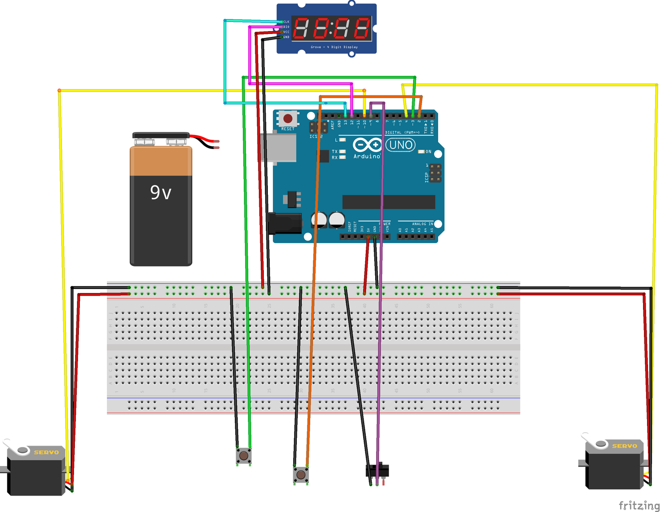
Coin operated timer in the USA HAD SO MANY PROBLEMS MANUFACTURER WOULD Circuit Diagram 1. 7-Segment Counter Circuit. This timer circuit is wired as an astable multivibrator to display a seven segment counter with the help of the counter IC CD 4033. This circuit is mostly added on to other circuits so as to make it more attractive by displaying a counter. The timer circuit is used to trigger the counter IC, which in turn advances Hello Guys, In this tutorial part 2 I am going to show you how integrate a relay module to the system So let's get started :)Find electronic components on sh

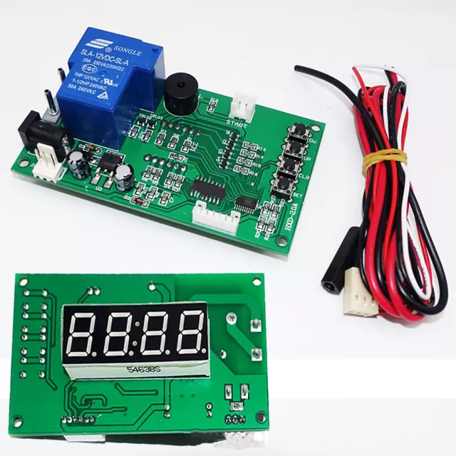
The board we have combined with the coin-operated device (you can see to two units connected in Fig. 2) is basically an interface between the user and the device equipped with 3 keys, a 4-way dip switch and a jumper allowing to configure the unit; moreover, the board reads the status of the open-collector outputs of the coin-operated device and Now its time to make a circuit to test the timer. My favorite circuit to use it the astable oscillator. It turns the timer into an oscillator that can blink LEDs or make sounds. You will need 2 resistors 1k ohms or larger, a capacitor and some sort of output or measurement device. I used an LED and a little piezoelectric speaker.
25+ Simple and Advanced 555 Projects Circuit Diagram
These have simple a simple switch or opto-interrupter that gives a momentary signal when a coin rolls by. The coin discrimination is done by mechanical means. For a non-critical project like this, you could also roll your own by fabricating a coin-guide/slot and using a simple opto-interrupter to make the signal as the coin goes rolling by.
Make connections on the rear by soldering point to point with the 30 AWG wire wrap wire . Follow the first circuit diagram. 2. Layout the coin counter and summing circuit on the second pcb board. Make connections on the rear by soldering point to point with the 30 AWG wire wrap wire . Follow the second, third and fourth circuit diagram. 3. The circuit board we have combined with the coin-operated device ( you can see to two units connected in Fig. 2) is basically an interface between the exploiter and the device equipped with 3 keys, a 4-way dip switch and a jumper allowing to configure the unit of measurement ; furthermore, the board reads the condition of the open-collector
Shot Timer with Relay at Output Circuit Diagram
In astable mode, the output from the 555 timer is a continuous pulse waveform of a specific frequency that depends on the values of the two resistors (R A and R B) and capacitor (C) used in the circuit (fig 1) according to the equation below.Astable mode is closely related to monostable mode (discussed in step 2), you can see that the schematic is nearly the same.
