Circuit of regenerative braking Circuit Diagram regenerative braking starts. •The peak current from simulation is around 0.5Amps @ 70% duty cycle. This translates to 24V * 0.5 Amps = 12 Watts. Since brake force is proportional to the current, this is the point of maximum brake force. •Beyond that point, the current starts to fall, mainly because of the motor construction (resistance and

Learn how electric vehicles recover the kinetic energy dissipated as heat during braking using regenerative braking. Understand how a motor acts as a generator and how the motor controller operates to store the recovered energy in battery or capacitor. There are two circuits in the hydraulic circuit of the regenerative braking system: the driving circuit and the drain circuit. The driving circuit includes a two-position four-way valve in addition to a cartridge valve, which is a one-way valve. The secondary component uses a pump or motor to direct the flow of oil from the reservoir to the

PDF Implementation of Regenerative Brake System Controller by Using Mini ... Circuit Diagram
Regenerative braking is implemented in conjunction with anti-lock braking systems (ABS), so the regenerative braking controller is similar to an ABS controller, which monitors the rotational speed of the wheels and the difference in that speed from. one wheel to another. In vehicles that use these kinds of brakes, the brake controller not only monitors the speed of the wheels, but it can regenerative braking is the only way to charge the battery without another mechanical connection, Not only it does improve fuel efficiency in EV, but also it can be adapted for Fig. Circuit diagram for Regenerative Braking action. Fig. Voltage waveform for regenerative Braking action
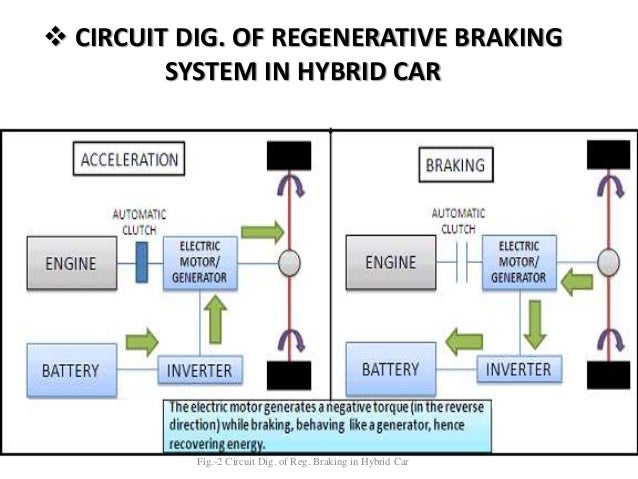
regenerative braking system on a BLDC motor using a Buck-Boost converter with micro control, which will serve as an electric car braking mechanism. Figure 1. Regenerative brake block schematic . Figure 2. Regenerative brake diagram . 2. Research Methodology The objective of designing this regenerative braking circuit is to streamline the device Contents: Applications of Regenerative Braking; Regenerative Braking in DC Shunt Motors; Regenerative Braking in DC Series Motors; Under this condition, the back emf E b of the motor is greater than the supply voltage V, which reverses the direction of motor armature current. The machine now begins to operate as a generator and the energy generated is supplied to the source. Regenerative braking slows down the vehicle by utilizing kinetic energy of the rotating wheels to charge the battery of the vehicle. Continue reading to know more about its principle, construction, and working. In this article, we're going to discuss: What is regenerative braking system? 1.1. Working principle: