Big Solar Tracker For ArduinoStudio Learning DIY FULL KIT Circuit Diagram Here, we will be monitoring the output voltage, current, and power of the panel using the ESP32 IoT development board. Choosing the Right Components for IoT Enabled Solar Power Monitor. With a solar monitor, it becomes very easy to monitor and detect faults in any solar system. This is why component selection becomes a very important part when Hello and Welcome to The IoT Projects. In this article, you will learn to make a Dual Axis Solar Tracker Arduino Project Using LDR and Servo Motors in Step by Step manner. In this project, we are going to use some Light Sensitive Sensors like (LDR) to track the sunlight and direct the solar panels towards the areas that Increase their efficiency. TITLE PET TRACKING SYSTEM USING IOT ACADEMIC SESSION: 2019/2020 (CAPITAL LETTERS) hereby agree that this Thesis* shall be kept at the Centre for Academic Information Services, Universiti Malaysia Sarawak, subject to the following terms and conditions: 1. The Thesis is solely owned by Universiti Malaysia Sarawak
and build internet of things on solar tracker. The platform that has been use in this project is Raspberry Pi 3 (RPi3). In this paper [10-11], the researcher is focusing on build dual-axis solar tracking system using programmable logical controller (PLC) based on automatic tracking system. The function of PLC in this research is to control
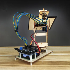
Dual Axis Solar Tracker Arduino Project Using LDR & Servo Motors Circuit Diagram
The code controls the solar tracking system's operations after it is uploaded to the Arduino UNO, allowing for accurate and dynamic sun tracking. The efficiency of this code is seen in the hardware testing step that follows, when the system's motions are monitored to maximize energy collection by aligning the solar panels as optimally as In this research paper we are focusing on power output maximization by using IOT based dual axis solar tracker. The system is divided into two parts, hardware system and software system. Hardware system includes light dependent resistor (LDR) which is used for detecting the sun light, two servo motor which are used to move the solar panel and software system consist of coding by using HTML
The single most simple way of getting more energy out of a solar panel is to have it track the sun. In fact solar panels that track the sun create around 30% more energy per day than a fixed panel. With that kind of power increase you'd think everyone would be doing it, but there are some good reasons why it's not overly common. In this chapter, we leverage some of the IoT technologies to design and build an IoT-based solar tracker system, where an IoT application is proposed to control and monitor this system. (intensity of light) to track the sun for maximum power generation [15, 16]. The solar tracker system detects the sun position with the help of Light
PDF PET TRACKING SYSTEM USING IOT Circuit Diagram
The passively controlled solar tracker contains no sensors or actuators but changes its position based on heat from the Sun. By using gas with a low boiling point in a container mounted on hinges at its middle, similar to a see-saw, the solar panel can change its position based on the direction of heat from the Sun.
