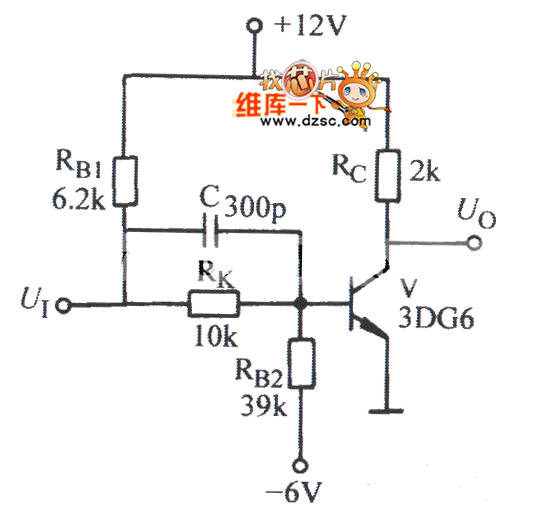
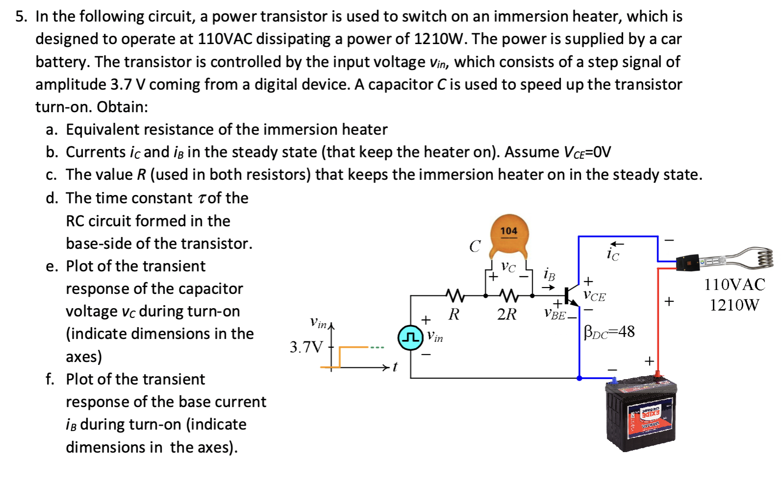
Amplifying current with high power transistor Circuit Diagram When we need to switch moderate to high levels of power, one of the best methods we can use is a transistor with an open-collector output. In this setup, we connect the emitter terminal of the transistor directly to ground. If we want to connect a load that requires a higher operating current demand of more than 3mA, it will burn the microcontroller. Many output devices will require a transistor switching circuit to operate a high current requirement load, such as relays, solenoids, and motors. How to use it?

For the transistor to operate as a switch, a principle of the small base current controlling the large collector load current is used. If you want to control large currents, use the Darlington transistor as a switch

Lab: Using a Transistor to Control a High Current Load Circuit Diagram
Introduction Transistors are often used as electronic switches, to control loads which require high voltage and current from a lower voltage and current. The most common example you'll see of this in a physical computing class is to use an output pin of a microcontroller to turn on a motor or other high current device. However, if you are delivering power to an entire circuit or a voltage-sensitive device, then you want to use a high-side switch. By the way, there are off-the-shelf components called " load switches." These ICs have a P-Channel MOSFET as the switching transistor with a built-in driver for that P-Channel.

These pins are meant to send control signals, not to act as power supplies. The most common way to control another direct current device from a microcontroller is to use a transistor. Transistors allow you to control the flow of a high-current circuit from a low-current source. Video: Transistor Schematics Video: Meet the motors

Low side vs. High side transistor switch Circuit Diagram
If this type of switching arrangement is acceptable, then the low-side switch is usually the cheapest way to achieve load switching. BJT Low-Side Switch A BJT can be used as a load switch and come in two flavors: NPN and PNP. For low-side switching, NPN transistors are used, and for high-side switching a PNP is used.
