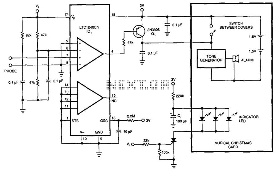
12 best water level sensor images on Pinterest Circuit Diagram Water Level Sensor Circuit. Working Explanation. The operating voltage of this circuit is 3 volts. When the required water level (or any other liquid) is detected through the probes it will activate the transistor. This will turn on the LED giving a visual indication of the water level detection. A 50K ohms variable resistor is used to adjust A water level sensor detects the presence or level of water by measuring changes in conductivity. It typically consists of a set of exposed conductive traces that act as probes. When water bridges the gaps between the traces, the sensor produces an electrical signal indicating water presence or level.

I need water level circuit. 1. Tank low, mid, high indication. 2. Sump/ground Tank low/ high indication. 3. CD-4001, 4093, 4017 IC. 4. Dry run indication. 5. Input sensor opto-coupler type. 6. Preferably low DC sensing voltage I have a water level sensor which gives me an output of 0-190ohm. It is connected to a gauge at 12V. Circuit Diagram for Water Level Sensor Module. The Schematic Diagram of the Water Level Sensor is shown below and as you can see it's pretty simple to understand.. In the schematic, the collector of the transistor is connected to the supply voltage of 5V, and the emitter is connected to the ground with a 100 Ohms resistor.
5 Simple Water Level Controller Circuits Circuit Diagram
This works by using water sensors that are set up in a stepwise manner at various depths inside the tank. When the water level goes up or down and touches these sensors, it sends a signal to indicate the current water level. In this post you are going to learn a simplest way to create simple water level indicator circuit using BJT BC547 only.. Overview. This article explores a water level alert circuit using a 555 timer and a float sensor, designed to detect and signal when water reaches a predefined level. The NE555 timer IC is a versatile and cost-effective solution for creating automated alert systems.This project is ideal for applications like water tanks, reservoirs, or flood detection systems.
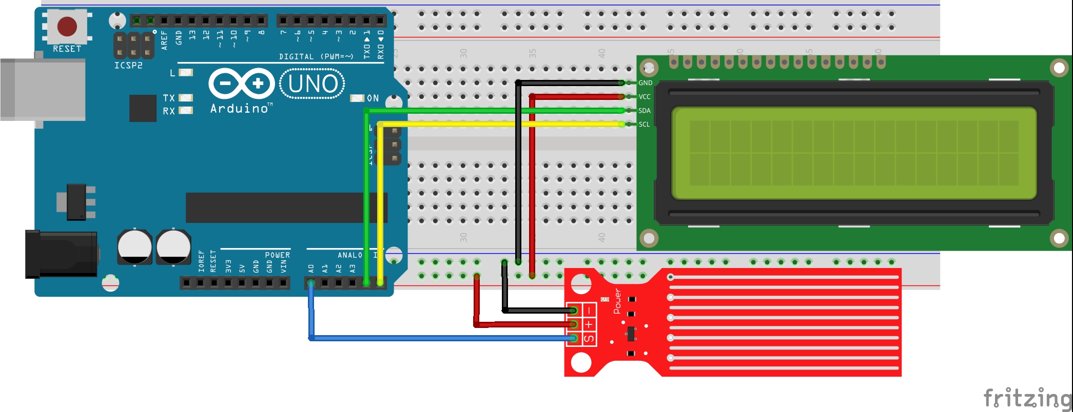
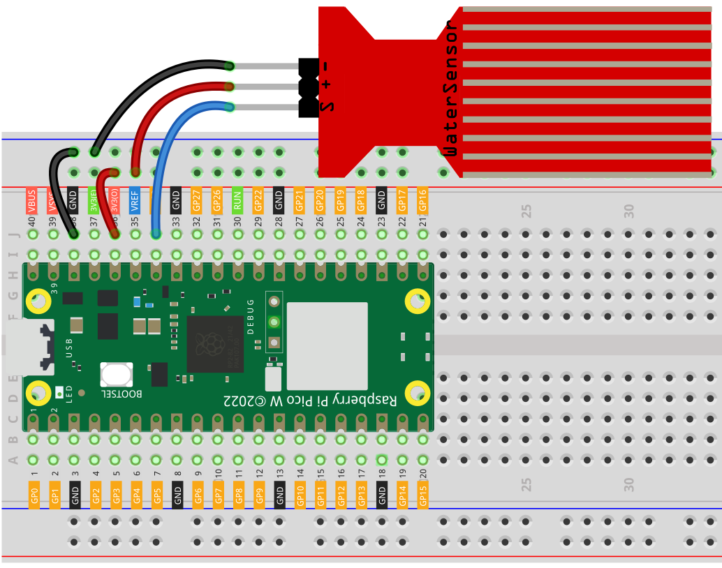
Learn how to use the water sensor with Arduino, how to detect the water leakage, rainfall, tank overflow, how to measure the water level, how to calibrate the water sensor, how water sensor works, how to connect water sensor to Arduino, how to code for water sensor using Arduino, how to program Arduino step by step. The detail instruction, code, wiring diagram, video tutorial, line-by-line This is a tutorial to build a simple water level indicator alarm circuit using transistors. It indicates different levels of water and raise an alarm upon getting the tank full. Sensors and Transducers Semiconductors Test Products Tools Projects 555 Timer Circuits Op-amp Circuits Audio Circuits Power Supply Circuits VLSI Projects All Generally, water stored in overhead tank is wasted due to over flow ,when the tank is full. Water level alarm using micro-controllers like 8051 and AVR are shown in previous articles.This article shows simple circuits of water level indicator with alarm.. Three circuits were shown here are simple and built using transistors, 555 timer and ULN2003 IC.